


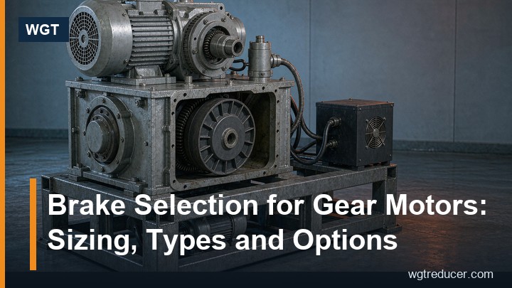
Brake Selection for Gear Motors: Sizing, Types and Options
Most gear motors that stop, hold or position a load need a brake, and almost every brake problem in the field traces back to the selection step rather than the product. A brake chosen from a catalogue column without checking the inertia, the duty and the switching method either wears out in months, fails to stop the load in time, or - on hoisting and inclined duties - fails to hold when the power drops. Getting the brake selection right the first time is mostly a matter of five decisions: failsafe principle, brake type, torque size, mounting position and control method.
This guide walks through each decision the way a drive engineer would: why spring-applied brakes dominate, what DC versus AC coils actually change, how to size the braking torque with the load inertia included, why the brake usually sits on the motor rather than the gearbox, and which control details make the difference between a brake that feels instant and one that feels lazy.
Why a Gear Motor Needs a Brake at All
Three duties put a brake on the specification. The first is holding: a hoist, a vertical screw, a gate or an inclined conveyor must stay put when the motor is switched off, and a self-locking worm stage cannot always be relied on to provide that holding, especially after wear or at ratios that are not truly self-locking. The second is stopping: a process machine that must reach a defined position within a cycle time cannot wait for the drive to coast down through the gearbox, and coasting time on a geared system is long because the load inertia, reflected through the ratio, dominates the motor shaft. The third is safety: an emergency stop or a guard-open interlock requires the motion to end in a defined time regardless of the load.
A VFD with controlled deceleration can cover some of this, but it cannot hold a load with the power off, and a VFD fault or a supply loss removes the deceleration exactly when it is needed most. That is why the mechanical brake remains the last line of defence on almost every serious gear motor application - and why brake selection is treated as a safety-relevant choice, not an accessory pick.
The Failsafe Principle: Spring-Applied, Power-Released
The industry standard for gear motor brakes is the spring-applied, electromagnetically released brake. The friction pack is compressed by coil springs all the time; applying current to the coil creates a magnetic field that pulls the armature plate off the friction disc and lets the shaft turn. Cut the current - by design, by a fault, or by a power cut - and the springs slam the armature back onto the friction pack within milliseconds.
This arrangement is chosen for one reason: it is inherently failsafe. Any loss of power produces braking, which is exactly the behaviour a hoist or an inclined conveyor needs. The alternatives do not have this property. A power-on brake releases the load the moment the control fails, and a hydraulic or pneumatic brake adds a second energy system that must itself be reliable. For the overwhelming majority of gear motor duties, the spring-applied electromagnetic brake is the only type worth specifying, so the rest of this guide assumes it.
DC or AC Coil: What the Difference Actually Means
Spring-applied brakes are offered with DC coils or AC coils fed through a rectifier, and the practical difference is less about the magnet and more about the response time and the wiring.
A DC coil brake is fed with rectified, smoothed voltage. Once the current is interrupted, the magnetic field decays through the coil's own time constant, which can hold the armature engaged for tens or even hundreds of milliseconds. To get a fast response, the standard trick is an over-excitation rectifier: apply full voltage to build the field fast, then drop to the holding voltage electronically. Brakes specified this way release in tens of milliseconds and re-apply quickly.
An AC-fed brake with a simple rectifier is cheaper and simpler to wire, and for holding duty - where the brake only engages when the machine stops - the slower response is irrelevant. The response time only becomes a selection criterion when the brake is cycled for stopping duty in a process sequence, where every engagement delay adds to the cycle time or to the stopping distance.
One more practical difference matters at commissioning: an AC-fed brake through a rectifier can be switched on the AC side with a standard contactor, while a DC coil interruption needs attention to the induced voltage spike. Follow the brake manufacturer's wiring diagram; the rectifier type exists for a reason.
Sizing the Braking Torque
Braking torque is sized from two duties that are often confused. For holding duty, the brake must simply resist the load torque reflected to the brake shaft. For stopping duty, it must also absorb the kinetic energy of the rotating system: it decelerates the total inertia from running speed to zero in the required time. The working formula combines both:
T_b = (J_total x omega / t_stop) + T_load,reflected
where J_total is the total inertia reflected to the brake shaft (motor rotor plus load inertia divided by the ratio squared), omega is the angular speed at the brake shaft, t_stop is the required stopping time and T_load,reflected is the load torque the brake must hold. Two rules of thumb keep the result honest:
- For hoisting and vertical duties, the static holding requirement is usually multiplied by a safety factor of 1.5 to 2, because a slipping hoist brake is a safety incident, not a quality problem.
- The load inertia, reflected through the gearbox, often dominates the motor rotor inertia by a wide margin. Forgetting the reflected load inertia is the single most common sizing error: the brake looks adequate on nameplate torque and then fails to stop the machine in the specified time.
The table below shows how the duty changes the sizing basis:
| Duty | What the brake must do | Sizing basis | Typical margin |
|---|---|---|---|
| Horizontal conveyor, stop in cycle | Decelerate rotating system + load | Kinetic + load torque formula | 1.5x on computed torque |
| Inclined conveyor, hold when stopped | Resist load pull-back | Reflected load torque | 1.5-2x on static |
| Hoist / vertical lift | Hold load, arrest overshoot | Reflected load torque, failsafe critical | 2x on static, test required |
| Positioning axis, repeatability | Stop precisely each cycle | Kinetic formula with short t_stop | Fast rectifier mandatory |
| Fan / low-inertia machine | Stop after coast already acceptable | Minimal; brake mostly for hold | Nameplate usually sufficient |
A brake sized exactly at the computed torque runs hot and wears fast. A sensible margin above the calculation - not an enormous one, because an oversized brake on a light load stops the machine hard enough to shock the gearbox - is part of good brake selection.
Where the Brake Sits: Motor Shaft or Gearbox Shaft
On a standard gear motor the brake mounts on the non-drive end of the motor shaft, behind the motor, before the gearbox. This position has a decisive advantage: the brake sees the fast, low-torque side of the driveline. Because torque scales inversely with speed, a brake that must hold 900 Nm at the output drum only sees a few newton-metres at the motor shaft of a 20:1 gearbox - so a small, light, cheap brake does the holding, and its friction pack works at motor speed where the energy per engagement is modest.
Mounting the brake on the slow output shaft instead requires a brake sized for the full load torque, which means a physically large unit, a separate mounting, and friction surfaces that absorb far more energy per stop. Output-side brakes appear only where the application genuinely demands them - for example when the load must be held against reverse drive through the gearbox in a way the input-side brake cannot guarantee, or on machines where the gearbox is driven from elsewhere.
The input-side position has one consequence worth knowing: because the brake works through the gearbox, backlash and gear mesh clearances sit between the brake and the load. For a positioning axis that must stop within fractions of a degree, that lost motion matters and can justify an output-side or dual-brake arrangement despite the size penalty.
Holding Duty and the Backstop Question
On inclined conveyors, a common question is whether a brake is needed at all, or whether a backstop - a one-way clutch that prevents reverse rotation - is the better answer. The two devices do different jobs. A backstop prevents the load from running the conveyor backwards when power is off; it does nothing to stop the conveyor in a defined distance, and it does nothing when the drive is still powered. A brake does both, but it consumes friction life every time it engages.
The standard practice on inclined duties is to fit both when the application is serious: the backstop takes the routine holding job and never wears, and the brake handles controlled stops, emergency stops and maintenance locking. Fitting only a brake means its friction pack is holding the loaded conveyor for the entire life of the machine, which is well within its capability but uses up the wear allowance that stopping duty also needs.
Rectifiers, Response Time and Manual Release
Three control details decide how the brake behaves in service. The first is the rectifier type, as covered above: over-excitation rectifiers for fast cycling, simple rectifiers for hold-only duty. The second is the switching point: on a VFD-driven gear motor, the brake should normally close only after the drive has brought the motor to standstill or near it - closing the brake at full speed every cycle turns it into the machine's routine decelerator and wears it prematurely. Modern drives provide a brake-control logic output that sequences exactly this way, and wiring it correctly is part of brake selection, not an afterthought.
The third is the manual release. Every spring-applied brake should be ordered with a manual release lever, because when the power is off and the load must be moved - threading a new belt, rotating a mixer by hand, freeing a jam - the lever disengages the friction pack without tools. Omitting it saves a negligible amount of money and costs an hour of dismantling at the worst possible time.
Brake wear itself is visible and serviceable: the friction lining wears, the air gap between armature and coil grows, and at the wear limit marked on the brake the air gap must be reset or the friction pack replaced. Machines that cycle the brake frequently need this on a scheduled inspection; machines that only hold need it rarely. Either way, the check takes minutes with a feeler gauge.
A Selection Checklist
Work brake selection for a gear motor through this sequence and most field problems disappear before they start:
- Confirm the duty class: pure holding, routine stopping, emergency stopping, or positioning. The class drives every later choice.
- Compute the reflected load inertia and the reflected load torque at the brake shaft - not the nameplate torque alone.
- Apply the duty-specific margin: 1.5x for general stopping, up to 2x for hoisting and safety-critical holding.
- Choose the rectifier: simple for hold-only, over-excitation for fast cycling.
- Plan the switching logic with the drive: brake closes at standstill or near it, opens before torque builds.
- Order the manual release lever, and confirm the brake's frame-specific mounting on the motor's non-drive end.
- Put the air-gap check on the maintenance schedule, with the interval matched to the cycle frequency.
For a ready-made example of a gear motor family specified with brakes and encoders for positioning duties, see the H series gear motor page, where the brake option is ordered with the motor rather than added later.
Frequently Asked Questions
What happens if the brake torque is undersized?
The immediate symptom is a stopping distance longer than specified; on a holding duty the load may creep or the brake may hold until heat from a slipping engagement degrades the friction surface. On hoisting duty an undersized brake is a safety defect - the load can run away - which is why the 2x static margin and a functional load test are standard there.
Can a VFD replace a mechanical brake?
A VFD can decelerate the load but cannot hold it with the power off, and it provides no braking during a drive fault or supply loss. For any duty where the load must stay put unattended, the mechanical failsafe brake remains necessary; the VFD and the brake work together, with the drive handling routine deceleration and the brake handling hold and fail conditions.
Why does my brake chatter or release slowly?
Slow release usually points to the rectifier: a simple rectifier on a duty that needs over-excitation, or a coil fed at the wrong voltage. Chattering can come from a worn air gap outside its adjustment window or from switching the brake while the drive is still applying torque. Both are selection and wiring issues, not reasons to replace the gearbox.
How long does a gear motor brake last?
Friction life depends almost entirely on engagement energy and frequency. A brake that closes once per shift at low speed can last the life of the machine; the same brake cycling forty times an hour at full motor speed is a wear part inspected monthly. Size the energy per engagement correctly and the wear rate follows predictable, serviceable intervals.
Does the brake go before or after the gearbox?
Almost always before - on the motor's non-drive end - so the brake is small and cheap and works at low torque. After the gearbox (on the output shaft) the brake must be sized for full load torque and becomes large and expensive; it is specified only for positioning accuracy requirements or special reverse-holding cases.
Next Step
If a duty needs a brake but the sizing is uncertain, start from the load side: list the inertia, the static load torque, the required stopping time and the cycle rate, then use the online selection system to match a gear motor with the brake option built in. Specifying the brake with the gear motor - same frame, same order - guarantees the mounting, the rectifier and the release lever all arrive matched, and the stopping test at commissioning confirms the calculation before the machine goes into service.
