


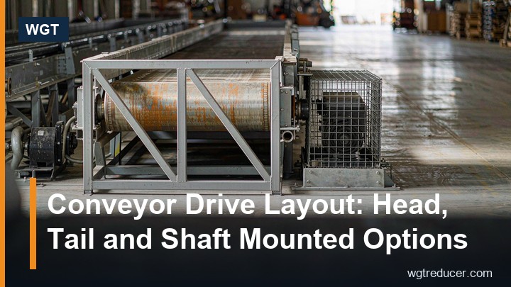
Conveyor Drive Layout: Head, Tail and Shaft Mounted Options
Every belt conveyor lives or dies by its drive layout. The same gearbox for belt conveyor duty can give years of quiet service in one arrangement and a lifetime of alignment grief in another, purely because of where it sits relative to the drum, the take-up and the access walkway. The choice is rarely about the reducer itself - a helical or bevel-helical unit does not care whether it drives a crusher or a belt - but about tension, overhung load, dirt exposure and how your maintenance crew reaches the coupling at two in the morning.
This guide walks through the three classic layouts: the head drive, the tail drive and the shaft-mounted hang-on unit, plus the hybrid arrangements that plant layouts keep forcing. Each has honest advantages and honest failure modes, and most conveyor problems that get blamed on "bad gearboxes" trace back to a layout chosen without weighing them.
Why Layout Decides Most Conveyor Drive Problems
A belt conveyor is a tension machine. The drive transmits torque into the belt through friction on the wrap of the drive drum, so the effective tension the drum can deliver follows the classic belt-friction relation: the tighter the slack side (thanks to the take-up) and the larger the wrap angle, the more torque the same drum can pass into the belt. Drive placement determines which side of the belt is tight and how the take-up has to be arranged - and therefore whether a given reducer rating is comfortably inside its envelope or silently living at its limit.
Three consequences follow, and they explain most of the layout advice below:
- Wrap angle is free performance. Moving the drive to a position with a snub pulley or a dual-drum arrangement increases wrap without a bigger motor.
- Overhung loads follow placement. A reducer hung directly on the drum shaft sees the drum's weight and belt pull as a cantilever load; a pedestal-mounted unit behind a coupling does not.
- Access dictates maintenance quality. The best-spec drive fails early if the coupling cannot be realigned or the oil checked without scaffolding.
| Layout question | What it controls | Common consequence of ignoring it |
|---|---|---|
| Head vs tail position | Which belt span is tight | Belt slipping at start-up under load |
| Pedestal vs shaft-mounted | Overhung load on reducer shaft | Early output bearing failure |
| Drive drum wrap angle | Torque per unit belt tension | Take-up permanently run to its end stop |
| Access side | Routine service quality | Couplings left misaligned for years |
The Head Drive: The Default for a Reason
The standard layout places the drive at the discharge end - the head of the conveyor. The carrying run between tail and head is the tight span, the drive drum pulls the loaded belt up the incline, and the return run carries the slack side back to the tail take-up. Almost every general-purpose conveyor built in the last century defaults to this arrangement, and the reasons hold up:
- Maximum friction for minimum take-up travel. The loaded, tight side meets the drive drum, so the tension differential across the drum is used efficiently.
- Spillage falls away from the product. At the discharge point, material is leaving the belt anyway; drips and dust from the drive area land where material lands regardless.
- Electrical proximity. The head end is usually where the control panel and the discharge chute live, keeping cable runs short.
The mechanical build is equally conventional: motor, coupling, reducer, then either a direct drum shaft or a second coupling to the drive pulley. For most medium-duty conveyors this is where a compact inline helical unit earns its keep - our R series inline helical gear reducers, for instance, mount on a torque arm or a pedestal behind the head drum and keep the whole drive train on one straight line, which is exactly what you want on the layout where alignment tolerance is tightest.
Head drives do have a known weakness: everything concentrates at one end of the structure. Long conveyors put a lot of steel and a lot of load at the head, and maintenance platforms, guards and electrical gear all crowd the same corner. On long-overland belts that crowding is precisely what pushes designers toward alternative layouts.
The Tail Drive: When the Plant Forces It
A tail drive - the reducer at the loading end - is unusual, but plants force it regularly: the head end may face a crusher housing, a building wall or an existing chute that cannot move, leaving only the tail free. A tail drive inverts the tension picture: the drive now pulls against the return run, the loaded span becomes the slack side, and the take-up has to generate more pretension to deliver the same friction on the drum.
That pretension is the tail drive's whole cost. Every bearing, every idler and the belt itself runs at higher tension for the same conveyed load, so a tail-driven conveyor needs a heavier belt, bigger idler ratings and a take-up that will actually be maintained - a gravity take-up earns its space here, because a screw take-up that nobody re-tensions quietly converts the layout penalty into belt slip.
Two rules make tail drives survivable:
- Increase wrap, not just tension. A snub pulley behind the drive drum - turning a 180° wrap into 210–240° - recovers much of the friction the layout lost, usually more cheaply than upsizing the belt.
- Derate for load-start. A tail drive starts against the full load with the tight side elsewhere, so the service factor discussion is not optional; soft-start or VFD starting is strongly preferred over across-the-line.
The Shaft-Mounted Hang-On Reducer
The third classic layout skips the pedestal entirely: the reducer clamps directly onto the drive drum's extended shaft and hangs there, restrained by a torque arm anchored to the structure. Belt pull and drum weight pass through the reducer's own output housing into the drum shaft, and there is no output coupling, no extra bearings and - critically - no alignment job at installation. You slide the bored housing onto the shaft, lock the bushing, bolt the torque arm, done.
This is why shaft-mounted reducers dominate aggregate, mining and port conveyors: they are the fastest reducer to replace in the field. A unit that seizes on a Friday night can be swapped by two fitters before Monday's shift, because the spare bolts onto the same drum shaft with nothing to re-align. On dusty, remote or mobile equipment where survey-grade alignment is fantasy, that robustness is the deciding argument - our S series helical worm shaft-mounted gear reducers with hollow output and integral bushing are built exactly for this duty, and the same logic extends across the RX frame sizes for larger torque.
The honest trade-offs are just as clear:
- The drum shaft carries everything. The reducer's full weight and the belt's pull act on the drum's outboard bearing, so the pulley and its bearings must be selected for the combined overhung load - not just the belt tension.
- Seal exposure. The hang-on housing sits directly above the dirtiest part of the conveyor, under the belt at the drive drum where dust and spillage concentrate; labyrinth or heavily-labyrinthed seals repay their cost immediately.
- Backstops need care. Inclined conveyors usually need a backstop to prevent runaway on shutdown; on a hang-on unit it lives inside or on the reducer, so its rotation direction must be confirmed at installation - a reversed backstop is a legendary field failure.
- The torque arm is a tuned part. Its length and anchor position set the reaction load into the structure; a "stiffened" torque arm welded to the nearest beam instead of the designed bracket overloads both the beam and the reducer housing.
| Criterion | Pedestal (head/tail) | Shaft-mounted |
|---|---|---|
| Installation alignment | Full coupling alignment required | None - clamps to drum shaft |
| Replacement time | Hours, with alignment | Minutes to hours, no alignment |
| Overhung load path | Into pedestal | Into drum shaft and bearings |
| Seal environment | Better - offset from belt | Worst - directly at drive drum |
| Best duty | Plant conveyors, clean areas | Aggregate, mining, mobile, remote |
Sizing the Drive on a Conveyor
Whatever the layout, the sizing sequence is the same, and it rewards honesty at each step:
- Effective tension. Add up the resistances - friction of idlers and return side, lift of the incline, and acceleration at start. The start case, with belt stretch and full load, is usually 1.3–1.5 times the running figure.
- Drive drum torque. Effective tension times drum radius, corrected by the wrap and friction margin from the layout choice above.
- Reducer rating with service factor. Apply the duty class: continuous conveyors with frequent starts need more than the catalogue "8 h/day" basis implies.
- Overhung load check. If anything - drum, sprocket, another pulley - hangs on the reducer's output shaft, verify the shaft's cantilever capacity at the actual load position. This is the step most often skipped and the one that produces the most mystery bearing failures.
- Mounting and environment. Dust class, ambient temperature and washdown duty decide seal package, paint system and breathers before anything is ordered.
The WGT online selection system takes power, speed and service factor directly and returns candidate frames with ratios and mounting variants, which is the quickest way to shortlist before committing to drawings.
Common Layout Mistakes in the Field
Walk enough conveyor installations and the same mistakes recur, nearly all of them layout decisions rather than gearbox defects:
- Reducer hung where it cannot be serviced. A shaft-mounted unit buried under the chute means oil checks get skipped until the bearings speak for themselves. If the layout forces this, specify long-life synthetic fill and extended breathers at purchase, not at failure.
- Take-up neglected. A screw take-up run to its end stop on a tail-driven conveyor is a slip waiting for a humid day. Mark the take-up position and make "take-up at 50% travel" a standing inspection item.
- Torque arm improvisation. The hang-on unit's torque arm bolted to whatever is nearby changes the reaction geometry; housings crack at the output flange on exactly these installations.
- Ignoring thermal derating on hot duty. A drive sited near a kiln or in a hot ambient loses catalogue capacity; a frame selected on room-temperature tables then runs hot oil and short seal life.
- Backstop direction unverified. True for every inclined conveyor, but most often bitten on shaft-mounted units where the backstop lives inside the hang-on housing.
None of these are exotic. They are all cheaper to fix on the drawing than on the structure.
Matching Reducer Series to Layout
A short cross-reference helps when the layout is already fixed:
| Layout | Natural reducer family | Why |
|---|---|---|
| Head drive, medium duty | Inline helical (R series) | Straight-through shaft, compact, efficient |
| Head drive with right-angle constraint | Helical bevel (K series) | Turns 90° where the motor must sit sideways |
| Shaft-mounted tail/hang-on | Helical worm with hollow shaft (S/SA series) | Bored housing, bushing clamp, no coupling |
| Heavy inclined, backstop needed | Bevel helical (B series) | High service factors, integral backstop options |
Keeping one family across a conveyor fleet also spares inventory: the same oil, the same seals and the same spare shaft seals cover several frame sizes, which quietly matters more in a plant with forty conveyors than a few points of efficiency on paper.
FAQ
Where should the drive be placed on an inclined conveyor?
At the head (discharge end) whenever the structure allows. The loaded tight span meets the drive drum, so the same reducer delivers more torque for the same take-up tension. Tail drives work, but they demand a heavier belt, a real take-up and a snub pulley to recover wrap.
Can one reducer drive two drums?
Yes - the dual-drum head drive shares torque through a coupling or a spur gear pass between drums and gains wrap angle on the belt. It adds alignment complexity and needs matched drum diameters, so it earns its place mainly on long, high-tension overland belts.
Why does a shaft-mounted reducer not need alignment?
Because its bored housing clamps directly onto the extended drum shaft - the drum's own bearings locate the shaft, and the torque arm only resists rotation. There is no separate output coupling to align, which is exactly why field replacement is so fast.
How much service factor should a conveyor drive carry?
Enough to cover the start case: frequent starts under full load and shock-prone duty typically justify a service factor of 1.5 or higher, while a steady, gently-started plant conveyor may run comfortably at 1.25. Size on the real starting tension, not the running figure.
Get a Conveyor Drive Sized to Your Layout
Send us the belt width, speed, incline and duty cycle - and the layout you are planning, head, tail or shaft-mounted - and we will return a sized proposal with the mounting package to match. If you already know your duty point, the online selection system will shortlist frames in minutes, and our team can confirm the overhung load and backstop details before you order.
