


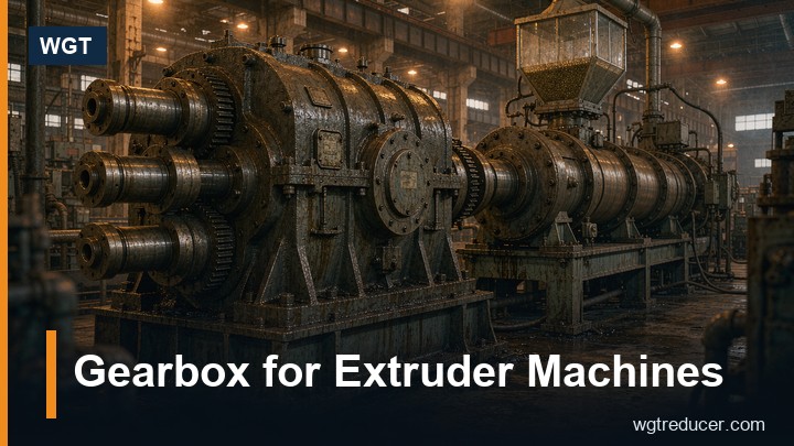
Gearbox for Extruder Machines: Thrust and Duty Selection | WGT
An extruder gearbox lives between a motor running flat out and a screw that turns slowly under enormous axial pressure. That combination - high input power, deep reduction, and a machine that pushes back along the shaft - is why extruder drives are specified differently from ordinary reducers, and why an undersized or casually selected unit announces itself within months. This guide sets out what the duty actually demands, how the drive is normally built, and what the enquiry should contain.
What Makes an Extruder Drive Different
Three things separate the duty from general power transmission. First, the thrust: the screw converts motor power into pressure, and that pressure pushes the screw - and therefore the gearbox output shaft - backwards with a force that can reach several tonnes on a mid-size machine. Second, the ratio: a screw turning at 20 to 120 rpm against a 1,500 rpm motor means reductions from about 12:1 to 75:1, deep enough that a single helical pair cannot cover it economically. Third, the duty cycle: extruders run continuously at rated load, sometimes for weeks between stops, and the thermal rating matters as much as the mechanical one.
The consequence is that an extruder gearbox is chosen by three numbers in tension with each other - torque, thrust and heat - and the frame that satisfies one may not satisfy the others.
Thrust: The Number That Sizes the Case
Screw pressure acts on the extruder's own thrust bearing in many machines, but on a very large number of drives - single-screw machines in particular - the gearbox output bearing carries it. Where the gearbox carries the thrust, its axial rating is a primary selection input, not a footnote.
Estimate it honestly. Thrust on the screw is roughly the melt pressure times the screw area: a 90 mm screw at 800 bar sees on the order of 50 kN pushing back, and larger screws see proportionally more. If the machine has its own thrust bearing ahead of the gearbox, state that clearly - the two designs are built differently, and a supplier who assumes the wrong case will quote the wrong bearings.
The failure mode of getting this wrong is characteristic: the gearbox runs fine on torque, and then the output bearing starts to noise at six to eighteen months as the thrust load cycles it beyond its rating. Plants often misread this as a lubrication problem. It is a selection problem, and it was decided the day the thrust figure was left off the enquiry.
Ratio and the Three-Stage Parallel Build
Deep ratios with continuous thermal load favour a three-stage helical build on parallel axes. Each stage shares the reduction, each mesh works near efficient geometry, and the case length stays inside what an extruder line can host. A large-frame three-stage industrial gear unit is the classic choice for mid-size single-screw machines and many twin-screw drives as well.
The input end matters as much as the output. Extruder motors are started against a screw full of polymer, so the starting method - direct, star-delta, soft-start or inverter - changes the torque the first stage must absorb. On inverter duty, the input stage also sees a wider speed range, and the lubrication must work at the bottom of that range, which is a real constraint on splash-fed units running slow for long periods.
Output speed tolerance is the last ratio question. Extrusion processes are sensitive to screw speed: a drive that hunts or slips under load shows up directly in the product dimensions. Stating the tolerance the process accepts on the enquiry is what keeps the selection honest.
Thermal Duty: Where Extruder Gearboxes Actually Fail
Mechanically, helical stages in a well-sized case rarely fail. Thermally, extruder drives are marginal by design, because they run continuously at high power in rooms that are often warm from the process itself. The thermal rating - the power the unit can dissipate forever without exceeding its oil temperature limit - is the ceiling that matters, and it must be checked at the true ambient of the extruder hall, not at catalogue room temperature.
The levers, in the order they should be used:
| Measure | Effect | Cost |
|---|---|---|
| Correct frame for continuous torque | Adequate case surface area to sink the heat | The frame you needed anyway |
| Synthetic oil | Better film at temperature, longer oil life | Marginal |
| Forced cooling on the unit (fan or coil) | Lifts thermal rating substantially | Moderate, needs services |
| One frame up for thermal reasons | Solves marginal cases outright | Frame price difference |
A practical habit: at commissioning, record the sump temperature after four hours at full load. That number becomes the baseline for every later reading, and a rise against it is the earliest warning the plant will get.
Material and Build Details That Matter
Extruder halls are warmer, dustier and sometimes chemically aggressive, so the fittings deserve specification rather than defaults:
- Breather sited and filtered for the hall's dust, or replaced with a sealed expansion arrangement where washdown reaches the unit.
- Seals specified for the true case temperature - a standard lip material that is adequate at 60 °C sump temperature is not adequate at 90 °C.
- Paint and hardware chosen for the chemistry in play, particularly on compounding lines where additives escape.
- Shaft interfaces matched to the screw drive coupling, with the coupling's own mass and any overhang stated - overhang on the output end loads the bearings through a lever the rating does not see.
None of these are expensive at order time. All of them are expensive as retrofits.
Sizing Walkthrough
A worked example shows how the numbers interact. Take a single-screw extruder with a 55 kW motor at 1,480 rpm and a screw speed of 60 rpm. The ratio is 1,480 / 60 = 24.7, so a ratio near 25:1 is drawn from the three-stage band. The continuous torque at the screw is modest for the frame, but the thrust - say the gearbox carries the full screw reaction - and the thermal duty at 55 kW continuous in a 40 °C hall decide the frame. In practice that often means the frame is one size above what the torque alone would suggest, and the extra case is the cheapest insurance in the plant.
The same arithmetic for a twin-screw machine differs in one respect: the distribution gearbox and the thrust arrangements are usually part of the machine builder's package, and the industrial gear unit is the speed reducer ahead of it. Stating which architecture the machine uses prevents the enquiry from being answered against the wrong drawing.
What the Enquiry Should Carry
A one-pass enquiry for an extruder gearbox contains:
- Motor power, speed and starting method, plus the inverter range if inverter duty.
- Required screw speed and the tolerance the process accepts.
- Who carries the thrust - the gearbox or the machine's own thrust bearing - and the thrust figure if it is the gearbox.
- Continuous operating hours per day and the true hall ambient.
- Output shaft details and the coupling arrangement, including any overhang.
- The environment: dust, washdown, chemical exposure.
That list lets the supplier confirm the frame against torque, thrust and heat in one pass - and the online selection system reflects the same inputs for standard builds.
FAQ
Can a standard industrial gearbox be used on an extruder?
Yes, when the thrust is carried elsewhere and the thermal rating checks out at the true ambient. The cases that fail are the ones where the thrust silently lands on a unit whose output bearings were never rated for it, or where the continuous thermal load was checked at catalogue ambient.
Why does my extruder gearbox run hot but still make product?
Oil temperature above the design limit does not stop production; it shortens life. Every extra 10 °C roughly halves oil service life and thins the film the bearings rely on. A unit that runs hot is spending its own future, and the fix is usually thermal: oil, cooling or one frame up.
How is thrust calculated for the enquiry?
Melt pressure times screw area, plus the friction and side loads the screw sees. The extruder maker will have the figure; if the gearbox output bearing is to carry it, the number goes on the enquiry explicitly.
Direct drive or geared - where is the line?
Low-speed, high-torque screws almost always need a gear stage; the question is how many stages. Deep ratios at continuous thermal load sit naturally in three-stage helical builds, which keep each mesh efficient and the case compact.
What maintenance does an extruder gearbox need?
Oil changes on schedule against the true sump temperature, a quarterly temperature log against the commissioning baseline, and standard checks on seals and breathers. Units carrying thrust deserve a listening check on the output bearing at each service - noise there is the early sign of a thrust rating that was too low.
Summary
An extruder gearbox is chosen by three numbers - torque, thrust and heat - and the one most often left off the enquiry is the one that fails first. State the thrust path, check the thermal rating at the real hall ambient, and let the frame follow those two figures. Do that, and the drive becomes the quiet part of the extrusion line: the machine runs, the product holds dimension, and the gearbox is discussed at the annual oil change, never at three in the morning.
