


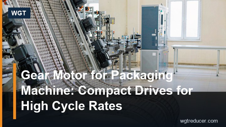
Gear Motor for Packaging Machine: Compact Drives for High Cycle Rates
A packaging machine does not fail because the gearbox is too small on average torque. It fails because the drive must start and stop thousands of times a shift, and each of those reversals loads the gear teeth and the output bearing differently from a steady running duty. Sizing a gearbox for packaging machine service therefore starts with the cycle, not with the motor nameplate: how many starts per minute, how fast the index has to settle, and how much inertia the drive has to bring to rest at every stop.
This article covers what changes when a reducer moves from continuous duty to high-cycle indexing duty, and how to check a frame before you commit to it.
Why High Cycle Rates Break Continuous-Duty Assumptions
On a conveyor or a mill the reducer is selected on running torque with a service factor for shock. On a packaging line the same arithmetic gives the wrong answer, because the damaging event is not the running load - it is the stop.
Every stop has to absorb the kinetic energy of the machine's rotating and translating masses. That energy goes through the gear train as a torque spike at the moment the brake engages or the motor reverses, and it is proportional to the inertia of the driven parts, not to the average packaging throughput. A light machine running 60 indexes a minute can load its reducer harder than a heavier machine running 10.
Three consequences follow:
- The service factor for intermittent, reversing duty is higher than for uniform duty, and it is applied to the motor torque, not added afterwards as a safety margin.
- The output bearing sees a reversing radial load at the pulley or crank, which shortens grease life far faster than a steady load of the same magnitude.
- Thermal capacity matters less than mechanical capacity, because the duty cycle keeps the average heat generation low while the peak torque stays high.
The Duty Numbers to Collect First
Before any frame can be checked, six figures decide the answer. They are worth collecting in one pass on site, because each one rules out a different class of drive.
| Parameter | Why it decides the frame |
|---|---|
| Indexes per minute | Sets the number of starts per hour, which sets the intermittent service factor |
| Index angle and settle time | Decides whether a mechanical indexer or a gearmotor with a brake is the right architecture |
| Driven inertia (kg·m²) at the output shaft | Sets the stopping torque the reducer must transmit |
| Required output torque, peak and running | Peak torque sizes the gearing; running torque sizes the thermal check |
| Output speed and accuracy | Ratio band and backlash class |
| Environment: washdown, dust, ambient | Housing material, IP rating and paint finish |
If the inertia is not known, it can be estimated from the mass and radius of the rotating parts, and confirmed once the machine is built. Guessing low is the single most common cause of a packaging drive that eats itself in the first year.
Indexing Accuracy and Backlash
Packaging and labelling machines position a product to within a fraction of a millimetre, and the drive's backlash is part of that error budget. Backlash at the output shaft is the sum of the clearances in every mesh, referred up through the ratio, so a two-stage unit contributes less than a three-stage unit of the same quality.
For most packaging duties the practical answer is a precision helical or bevel-helical reducer with a stated backlash class, rather than a worm unit - worm gearing has useful self-locking properties but higher sliding losses and typically wider backlash. Where the machine genuinely needs near-zero backlash, a planetary servo gearbox or a cam indexer is the correct architecture and a general-purpose reducer should not be forced into that role.
Backlash is also a maintenance figure. A drive that has run two years at high cycle rates will have a wider backlash than its nameplate value, and the position tolerance the machine was set up with will have drifted. Recording the figure at commissioning gives the maintenance team a baseline.
Stopping Torque: the Calculation That Gets Skipped
The stopping torque is the inertia multiplied by the angular deceleration, added to whatever running load is present at the moment of the stop:
T_stop = J × (2π Δn / 60t) + T_load
where J is the total inertia reflected to the output shaft (kg·m²), Δn the speed change in r/min, t the stopping time in seconds, and T_load the running torque in N·m.
A worked example makes the point. Take a cartoning line whose indexing shaft carries a total reflected inertia of 0.8 kg·m², running at 45 r/min and required to stop in 0.12 s:
- Deceleration term: 0.8 × (2π × 45 / (60 × 0.12)) = 0.8 × 39.3 = 31.4 N·m
- Running load at the shaft: 20 N·m
- Stopping torque: 31.4 + 20 = 51.4 N·m
The reducer's running torque is only 20 N·m, but it must transmit 51.4 N·m sixty times a minute. A frame selected on the running figure alone would be roughly half the size it needs to be. Note also that a longer stopping time cuts the peak: stretching the stop from 0.12 s to 0.24 s halves the deceleration term.
The same three inputs - output speed, required torque and duty description - drive the frame check. If you want the ratio and frame candidates worked out before you talk to a supplier, the online gear reducer selection system takes motor speed, target output speed and machine type and returns candidate frames with the service factor already applied.
Matching the Reducer to the Machine Layout
Packaging lines are built out of short, tight modules, so the drive usually has to fit a footprint rather than the other way round.
Inline helical units suit a drive that runs along the machine axis - a conveyor module, a film-feed roller, a belt section. They are the quietest option at speed and the most efficient, which matters on a line with dozens of drives.
Right-angle bevel-helical units suit the case where the motor cannot stand out along the machine, which is most of the time on a line built against a wall or inside a guard. The 90-degree input turns the motor into the available space without changing the duty.
Hollow-shaft units remove the output coupling and shorten the drive train further. On a packaging machine the output shaft is often short and driven by its own bearings, which is exactly the case a hollow output suits, provided the shaft is stiff enough to carry the unit.
A compact representative of the second family is the M3RHF80 right angle gearbox, a size 80 three-stage unit with a bevel input and a hollow output - the arrangement chosen when a mid-size machine shaft needs a driven end and the motor has to sit off the machine axis. For a larger indexing shaft needing more capacity in the same layout, the M3PHF90 hollow shaft gear reducer carries the higher torque band.
Washdown, Dust and the Rest of the Environment
Food, pharmaceutical and beverage packaging lines are cleaned with water and sometimes with caustic solutions. The reducer is usually outside the wash envelope but close enough to be splashed, and a drive that rusts at its seals will contaminate the line.
The practical specification is a housing with a corrosion-resistant finish, seals rated for the wash pressure actually used, and a breather positioned so that water cannot enter when the case cools. Where high-pressure washdown is aimed at the drive, an IP65 or better enclosure and a stainless or coated housing are worth the cost, and the breather should be remote-mounted rather than sitting on top of the case.
Dust is the opposite problem. In dry-goods packaging the drive has to keep abrasive powder out of the seals, which points to a lip seal with a dust lip or a protective deflector at the output, and to grease selection rather than oil where the duty is slow and intermittent.
Service Factor for Intermittent Duty
Service factor is where most packaging-drive mistakes are made, because the standard tables are read from the wrong row. A drive that runs eight hours a shift is not a continuous duty if it starts and stops sixty times a minute; it is intermittent reversing duty, and the factor for that class is materially higher.
The factor is applied to the motor or running torque to give the design torque, and the frame is then chosen so that its rating meets or exceeds that design torque. The consequence is that a packaging drive is often one or two frame sizes larger than the same power rating on a conveyor - a fact worth stating up front to the buyer, because it looks like oversizing until the first year's service is counted.
Where the duty includes frequent plugging or regenerative braking, the factor rises again, and the thermal check should be repeated with the actual duty cycle rather than assumed continuous.
Making the Enquiry Productive
A supplier can only check a frame against real numbers. The enquiry that gets a correct answer quickly contains: the machine type and what it does, the motor power and speed, the required output speed, the peak and running torque at the output, the number of indexes or starts per minute, the environment, and any footprint limit.
With those figures the frame, ratio, service factor and mounting style all follow, and the drawing can be issued for the interface check before anything is ordered. WGT quotes industrial gear units in this way, supplies the outline drawing as a PDF for each frame, and ships factory-tested units in export crates with a one-year warranty.
Frequently Asked Questions
Why is the gearbox for a packaging machine often larger than the one on a conveyor of the same power?
Because the service factor follows the duty class, not the power. A drive that starts and stops thousands of times a shift is intermittent reversing duty, and its factor is higher than for uniform continuous duty. Applied to the running torque, that factor moves the selection up one or two frame sizes.
Can I use a standard helical reducer for an indexing axis?
Often yes, provided the stopping torque has been calculated, the service factor matches the reversing duty, and the backlash class suits the position accuracy the machine needs. Where the accuracy requirement is very tight, a planetary servo gearbox or a cam indexer is the correct architecture instead.
How do I estimate the inertia if I do not know it yet?
Break the driven parts into simple shapes and use the standard inertia formulas, then reflect everything to the output shaft through the square of the ratio. Treat the result as an estimate and confirm it once the machine is built - designing on a guessed-low inertia is the usual cause of early drive failure.
Does the output bearing need different treatment at high cycle rates?
Yes. A reversing radial load at the pulley or crank cycles the bearing far more often than a steady load, so grease life shortens and the inspection interval should be set from the cycle rate rather than from a calendar period.
What protection does a washdown environment require?
A corrosion-resistant housing finish, seals rated for the wash pressure actually used, and a breather positioned or remote-mounted so water cannot be drawn in as the case cools. Where high-pressure wash is aimed at the drive, specify IP65 or better.
Choose the Drive with the Cycle in Mind
If you are specifying a drive for a packaging or handling machine, send the machine type, motor power and speed, output speed, peak and running torque, and the number of starts per minute. WGT checks the frame against the duty class and returns the outline drawing, the confirmed ratio and a written quotation.
Use the online selection system for a first pass at the ratio and frame, then send the numbers across and we will confirm the unit for your cycle.
