


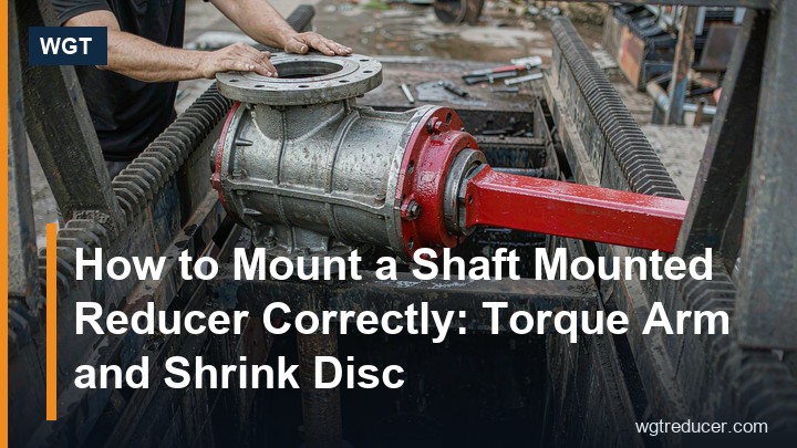
How to Mount a Shaft Mounted Reducer Correctly: Torque Arm and Shrink Disc
A shaft mounted reducer hangs directly on the driven machine shaft - no bedplate, no output coupling, no alignment shims. That is why conveyor, elevator and screw drive points use them, and it is also why a careless installation causes problems a foot-mounted drive never sees: the whole gear unit mass and the working torque both pass through one bore and one torque arm. This guide walks through mounting a shaft mounted reducer correctly, step by step, from receiving checks to the first running hours. If you are comparing units first, our shaft mounted torque arm gear units and torque arm industrial gear reducers cover the M-series frames discussed below, and the online selection system can pre-size the frame before you commit to a drawing.
Why Shaft Mounting Is Different from Foot Mounting
A foot-mounted gear unit sits on its own foundation. Its weight lands on concrete, its output torque reaches the machine through a coupling, and any installation error shows up as coupling misalignment you can dial in later. A shaft mounted reducer inverts that logic: the machine shaft becomes both the input support and the datum for the whole drive.
Three consequences follow, and each one becomes a checklist item later in this article:
- The bore carries everything. Gear unit weight, reaction torque and vibration all transfer through the fit between the output bore and the machine shaft. Surface condition and fit tolerance matter more than they ever would with a coupling.
- The torque arm is a structural member. Reaction torque has to leave the housing somewhere. The torque arm conducts it into the machine structure, and a weak or wrongly angled anchor turns the mounting into a lever problem.
- Assembly and removal are mechanical operations. Shrink discs or clamping elements grip the shaft by interference, so fitting and removal follow a bolt-tightening sequence, not a hammer-and-hope routine.
None of this is difficult, but each step has a failure mode that only appears after weeks of running. Working through them in order is the cheapest insurance available.
Pre-Installation Checks Before the Unit Touches the Shaft
Most mounting failures trace back to conditions that were visible before installation started. Check them while the gear unit is still on the pallet:
- Machine shaft condition. Clean the shaft seat completely and inspect for rust, scoring, paint or burrs. The fit is an interference fit by design; a few tenths of dirt change the clamping pressure and can let the unit creep on the shaft.
- Shaft diameter and tolerance. Measure the shaft at several points along the seat length. It must sit within the tolerance band printed on the gear unit's outline drawing - undersize shafts are the single most common cause of bore slippage reported in service.
- Rotation direction and output position. Confirm the required rotation direction and set the output shaft position before final tightening, since some backlash adjustment in the mounting angle is only available before the clamping element is torqued.
- Anchor point for the torque arm. Identify the structure that will take the reaction. It must be rigid in the direction of the reaction force and positioned so the torque arm sits near perpendicular to the reaction line at operating conditions.
- Oil level and breather position. Verify the oil level plug matches the mounting attitude and that the breather ends up on top. A shaft mounted reducer that hangs at an unplanned angle can run with a half-dry top bearing.
Skipping the shaft tolerance check is the classic mistake. Everything downstream - torque arm preload, shrink disc clamping, even the anti-rotation bracket - assumes the bore and shaft are in proper interference contact.
Fitting the Shrink Disc or Clamping Element
The clamping element is what turns a sliding fit into a torque-proof connection. On modern shaft mounted reducers it is usually a shrink disc: a tapered ring that is drawn over a hub when its locking screws are tightened in sequence, compressing the hollow output shaft onto the machine shaft.
The fitting sequence that works in the field:
- Slide the gear unit onto the clean, lightly oiled shaft (only the shaft - keep oil off the shrink disc tapers unless the manual says otherwise).
- Push the unit to the axial position shown on the drawing; the output hub should not overhang the shaft end, and the shaft should not bottom out inside the bore.
- Tighten the shrink disc screws progressively and diagonally across the ring, in the stages listed on the nameplate or drawing - typically in three passes up to the final torque, never one hard pass around.
- Confirm the gap or gauge dimension specified between shrink disc flanges after tightening. If the specified gap is not reached, the screws are not yet at full preload and the connection is not rated for full torque.
Reverse the logic for removal: release the screws in the same diagonal pattern, then use the removal screws provided to back the ring off. Never drive the gear unit off the shaft with a hammer through the housing - the gearing will remember it.
Setting Up the Torque Arm
The torque arm converts reaction torque into a pull or push on a fixed anchor. Mounted wrongly, it does something worse than transmitting force badly: it loads the housing in a direction the bearing arrangement was never designed for.
Set it up in this order:
- Swing the arm to the anchor. Most designs allow the arm to be clocked around the housing. Choose the position that keeps the arm closest to perpendicular with the reaction line through the full load cycle.
- Use the elastomer element as designed. Where the arm connects through a rubber buffer or spring element, that element is part of the torque path, not a convenience. It absorbs shock peaks; a worn or omitted buffer sends them into the housing instead.
- Anchor to structure, not sheet metal. The anchor point needs stiffness comparable to the torque it sees. A bracket welded to thin plating works loose, hammers, and eventually fatigues.
- Leave thermal and operational freedom. The arm must allow the gear unit small axial and angular movement as temperatures change. A rigid two-way lock at both ends of the arm turns the mounting into a bound frame.
One practical habit: after the first week of running, re-check the torque arm bolts and the shrink disc gap. Initial bedding-in settles interfaces slightly, and a five-minute re-torque at that point prevents most of the long-term creep cases.
The Anti-Rotation Bracket and Backstop Considerations
Some drives need more than a torque arm. On inclined conveyors and elevators, a backstop (anti-runback device) may be built into the gear unit, and a separate anti-rotation bracket may be specified so the housing cannot rotate at all during a stopped, loaded condition.
Check three things in this situation:
- The backstop direction must match the permitted rotation direction before the unit goes on the shaft - it cannot be changed in place on most designs.
- The anti-rotation bracket, where fitted, takes reaction during backstop engagement, which is often the highest instantaneous load the drive ever sees. Its anchor must be engineered for that event, not just for normal running.
- Both the torque arm and the bracket act on the same housing. Keep their lines of action separated as the drawing shows; paralleling them onto one anchor point distorts the load path.
If your application involves a loaded hold-back duty, say so at enquiry stage. The online selection system captures the duty class, and WGT confirms the backstop rating and bracket layout in writing with the quotation.
Commissioning: The First Running Hours
A shaft mounted reducer tells you within the first hours whether the mounting is right. Treat the start-up as part of the installation:
- Run empty first. A short unloaded run checks rotation direction, oil distribution and noise without load stress.
- Listen and feel. A correct installation runs quietly with no knocking. A rhythmic knock that changes with speed points to the torque arm or anchor; a high-pitched whine that fades as the housing warms is normal run-in.
- Check temperatures. Housing temperature should stabilise well below the limits on the data sheet. A climbing temperature trend on the output bearing end often means the bore is slipping microscopically - stop and re-clamp before damage starts.
- Re-torque everything once bedded in. Shrink disc screws, torque arm bolts, bracket bolts - one pass after the first week, then on the normal schedule.
Common Mounting Mistakes and What They Cost
| Mistake | Symptom later | Prevention |
|---|---|---|
| Dirty or undersized shaft seat | Bore creep, fretting, eventual shaft damage | Measure and clean; reject out-of-tolerance shafts |
| Shrink disc not fully tightened | Sudden loss of drive under load | Verify the specified flange gap after tightening |
| Torque arm anchored to flexible structure | Knocking, loose bolts, cracked bracket | Engineer the anchor for the reaction force |
| Rigid arm with no movement freedom | Bearing overload at the output end | Keep the designed elastomer and clearance |
| Wrong backstop direction | Redesign and unit swap after delivery | Confirm rotation at enquiry stage |
None of these cost much to prevent. All of them cost production hours to fix after the fact, and most of them appear not at start-up but weeks in, once bedding-in has done its work.
Summary: The Order of Operations
Mounting a shaft mounted reducer correctly reduces to a short, ordered list: verify the shaft, clean the seat, slide the unit on, position the output, tighten the shrink disc progressively and verify its gap, clock and anchor the torque arm with its elastomer intact, check any backstop and bracket, run empty, then re-torque after the first week. Each step protects the one interference fit and one reaction path that the whole concept depends on.
For help matching a shaft mounted unit to a specific drive point, WGT supplies outline drawings for every M-series frame and confirms selections in writing. Browse the torque arm gear units in the M-series range, or send the duty point through the online selection system for a checked quotation.
Frequently Asked Questions
How tight should the shrink disc screws be?
Tighten to the torque stamped on the shrink disc or given in the manual, in three progressive diagonal passes, and stop only when the specified gap between the ring flanges is reached. The gap - not the wrench click alone - is the proof of full preload.
Can a shaft mounted reducer be removed without damaging the shaft?
Yes. Release the shrink disc screws in the diagonal pattern and use the removal screws to back the ring off; the clamping element releases the interference and the unit slides off. Hammering the housing off is the one method guaranteed to damage both shaft and gearing.
Does the torque arm need any adjustment after installation?
Check it after the first week of running and re-torque its bolts, since interfaces bed in slightly. After that it needs inspection on the normal schedule, not adjustment - if it is knocking or its bolts keep loosening, the anchor structure, not the arm, is the problem.
What happens if the shaft is slightly undersize?
The clamping element cannot reach full interference and the bore may creep under torque, showing up as fretting and heat at the output end. Undersize shafts should be corrected before installation; there is no safe "a bit loose" condition on a shaft mount.
Which direction should the torque arm point?
As close to perpendicular to the reaction torque line as the design allows, anchored to rigid structure, with the elastomer element in place. The outline drawing shows the accepted positions; if none of them works in your layout, discuss it before ordering rather than improvising a bracket.
