


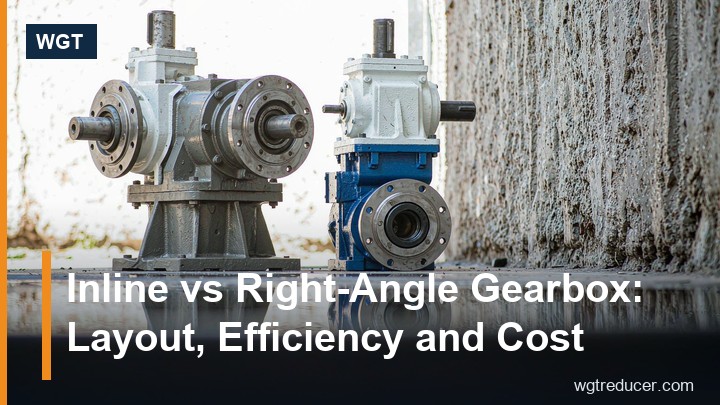
Inline vs Right-Angle Gearbox: Layout, Efficiency and Cost
Choosing between an inline and a right-angle gearbox is the first fork in almost every drive selection, and it is decided less by the catalogue than by the machine: where the motor can physically sit, how much efficiency you can afford to lose, and what the shaft alignment of the driven equipment looks like. This guide compares the two families on layout, efficiency, torque density, cost and maintenance, then gives a five-question check you can run against your own duty point before any model number is chosen.
Two Layouts, One Job
Every industrial gearbox does the same three things: it multiplies torque, divides speed, and bridges the mechanical gap between a fast, small motor and a slow, torque-hungry driven shaft. What distinguishes an inline unit from a right-angle unit is the path the power takes through the gear stages — and that path dictates the shape of the housing, the position of the motor, and how much of the motor's energy survives to the output.
Neither family is "better". A mixer drive with the motor hanging under the agitator tank wants one layout; a bucket elevator with the motor standing beside the head pulley wants the other. The comparison below is about recognising which constraints on your machine are hard, and letting those decide.
What "Inline" Actually Means
An inline (coaxial) gearbox keeps the input and output shafts on one centre line: motor, gearbox and driven shaft all sit on the same axis. Inside the housing, the stages are helical gear pairs — pinion after gear, shaft after shaft — so the power flows straight through. The WGT R series is the classic example: the R137 large inline helical gear reducer carries 137 mm of centre distance in a housing whose motor flange faces the output coupling directly.
A second inline variant is the parallel-shaft layout, where the output axis runs parallel to the motor axis but offset to one side. Functionally it behaves like a coaxial unit — all-helical stages, high efficiency, no direction change — but the offset output lets the drive hug a machine frame or drop into a narrow gap. The F37 parallel shaft helical gear unit is the small frame of this type: a two- or three-stage all-helical train in a rectangular envelope.
What "Right-Angle" Actually Means
A right-angle gearbox turns the power path by 90 degrees. Two gear technologies do this in mainstream industrial drives:
- Helical-bevel. A helical input stage feeds a bevel gear pair, so the output shaft exits at 90 degrees with rolling-contact efficiency at every mesh. The K series is the standard industrial form, and it keeps 94–96% efficiency across its whole ratio range.
- Helical-worm. A helical input stage feeds a worm and worm wheel. The worm does the direction change and a large share of the ratio, which pushes total ratios far higher (up to roughly 300:1) in a compact right-angle box — at the cost of the worm stage's sliding-contact losses. The S series helical-worm unit is this type, and the helical front stage is what keeps its efficiency respectable at moderate ratios.
The right-angle layout buys you one specific thing: the motor no longer has to sit behind the driven shaft. It can sit parallel to the machine frame, under a walkway, or flat against a wall — which is why right-angle units dominate confined machines and compact process skids.
Efficiency: Where the Power Goes
Efficiency is the clearest numerical difference between the families, and it comes entirely from the type of tooth contact in the decisive stage. Helical gears mesh in rolling contact, so losses stay in the low single digits. Worm threads slide against the wheel, and sliding generates heat instead of torque.
| Layout | Decisive stage | Typical efficiency | Loss mechanism |
|---|---|---|---|
| Inline coaxial (R/RX) | All helical | 94–96% | Rolling contact only |
| Parallel shaft (F) | All helical | 94–96% | Rolling contact only |
| Right-angle helical-bevel (K) | Bevel pair | 94–96% | Rolling contact |
| Right-angle helical-worm (S) | Worm wheel | Lower as ratio rises | Sliding contact in the worm stage |
Read the table with one caution: the worm-stage figure is not a single number. At a ratio of 10:1 the worm thread is coarse and efficiency is reasonable; at 80:1 the thread is fine and the losses climb steeply. That is exactly why the helical-worm design exists — the helical stage takes the first multiplication so the worm thread never has to run at an extreme ratio.
For a continuously running drive, the efficiency difference compounds into energy cost. A 7.5 kW motor running two shifts on a unit that wastes 4% more power than necessary burns roughly 480 kWh of extra electricity a year — often more than the price difference between the two layouts within the first two years.
Layout and Footprint: Space Is a Specification
The efficiency argument favours inline units; the layout argument usually favours right-angle ones. Three placement questions settle most real cases:
- Can the motor sit behind the driven shaft? If the machine end has free space, an inline unit gives the shortest overall drive train and a single shared mounting face for motor and gearbox.
- Is the drive axis across the machine or along it? Conveyor drives along the belt line suit inline or shaft-mounted layouts; drives that must turn a corner toward the machine frame suit the right-angle K or S families.
- Is the motor exposed to product, washdown or traffic? A right-angle unit lets the motor tuck out of the spray path or behind a guard, while an inline unit leaves it projecting into the aisle.
The parallel-shaft F series occupies a useful middle ground: all-helical efficiency with an offset output, so the drive fits beside the machine axis where a coaxial unit would protrude.
Cost, Stock and Serviceability
Purchase price follows the gear technology more than the layout. An all-helical inline unit and a helical-bevel right-angle unit of the same frame class are priced in the same band, because both are cut, hardened and ground gear sets in a cast-iron housing. A helical-worm unit of the same torque rating is usually the least expensive of the three, because the worm wheel is cheaper to produce than ground bevel gearing — which is one reason it remains the default in low-cost machinery.
Service behaviour differs in one practical way. Right-angle worm units run hotter, so their oil ages faster and seals see higher temperatures; budget for shorter oil-change intervals. Inline and helical-bevel units run cooler and are closer to "fit and forget" under normal duty — though every family still wants its first oil change at around 400 hours and periodic seal checks.
| Decision factor | Inline (R / F) | Right-angle helical-bevel (K) | Right-angle helical-worm (S) |
|---|---|---|---|
| Efficiency at typical ratios | 94–96% | 94–96% | Falls as ratio rises |
| Space along the drive axis | Longest | Short | Short |
| Space beside the shaft | Minimal | Motor sticks out sideways | Motor sticks out sideways |
| Ratio ceiling (single unit) | ~200:1 | ~200:1 | ~300:1 |
| Relative purchase cost | Medium | Medium | Lowest per torque |
| Heat load and oil aging | Low | Low | Highest |
How to Decide: A Five-Question Check
Run your duty point through these questions in order; the first hard answer usually ends the comparison:
- Is the ratio above roughly 60:1? If yes and the duty is continuous, start with the S series helical-worm family — a bevel or inline unit needs multiple stages to get there.
- Is energy cost or continuous duty dominant? If yes, stay all-helical: inline R for coaxial drives, parallel-shaft F for offset layouts, helical-bevel K if the motor must stand aside.
- Is the space beside the driven shaft free? If yes, a right-angle unit simplifies guarding and access; if not, the inline families win on envelope.
- Must the drive back-drive, or hold position? Worm stages resist back-driving at some ratios; helical and bevel stages back-drive freely. If the machine must hold, specify a motor brake regardless of family — never rely on the gearbox.
- Does an existing installation dictate the interface? Replacement projects are decided by shaft diameter, flange dimensions and centre height, not by preference. Match the old unit first; every WGT series is built to stable European centre distances precisely for this reason.
Questions of ratio, torque and frame size — the part that remains after the layout is fixed — can be worked through the online parametric selection system, which filters by torque, ratio and mounting and returns the frames that clear all constraints.
Frequently Asked Questions
Is an inline gearbox always more efficient than a right-angle one?
Not automatically. An inline unit and a helical-bevel right-angle unit both mesh in rolling contact at every stage, and their efficiencies are effectively the same 94–96%. Only the worm stage — in helical-worm right-angle units — introduces the sliding losses that pull efficiency down, and the penalty grows with the ratio.
Why choose a parallel-shaft unit instead of a coaxial inline one?
When the driven shaft sits beside rather than behind the motor. The parallel-shaft layout keeps the all-helical efficiency of an inline drive but offsets the output axis, so the gearbox fits against a machine wall or inside a narrow frame where a coaxial unit's motor would clash with the structure.
Are right-angle worm gearboxes cheaper for a reason I should worry about?
The lower price reflects the cheaper worm wheel, but the trade-offs are real: higher running temperature, faster oil aging and falling efficiency as the ratio climbs. For intermittent duty at moderate ratios the economics work well; for 24-hour duty at high ratios, an all-helical alternative usually repays its higher purchase price in energy.
Can I mix the decision — for example an inline unit with a right-angle output?
Yes, and it is common at larger ratios: combination units such as an R-series inline stage followed by a worm or bevel stage exist precisely for duties where one family alone is inefficient or too large. The design rule is to put the efficient stages first and let the final stage do only the direction change or the last multiplication.
If your duty point is already clear, the fastest path from torque and speed to a concrete frame is the online selection system. For help comparing a specific inline and right-angle option — or cross-checking a gearbox you already run — send the nameplate data and the driven-machine description, and our engineering team will come back with a confirmed selection and a factory quotation.
