


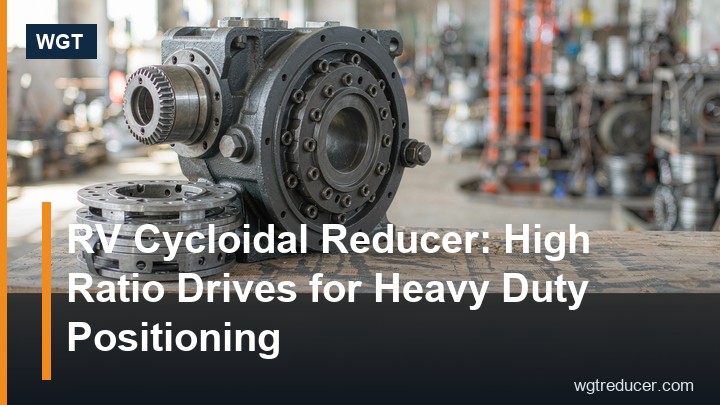
RV Cycloidal Reducer: High Ratio Drives for Heavy Duty Positioning
A cycloidal pin wheel reducer is the drive to reach for when a machine needs a large speed drop, a compact envelope and tolerance for shock loads in the same package. Where a worm gearbox trades efficiency for ratio and a helical unit needs several stages to climb the same reduction, the cycloidal principle delivers high ratio in one or two stages with most of its teeth sharing the load at any moment. That structural fact explains nearly everything about where these units are used - and where they are not worth the premium.
How the Cycloidal Mechanism Works
Inside the housing, the input shaft carries an eccentric. The eccentric turns a cycloid disc - a gear whose profile is not an involute but a true cycloid curve. As the input rotates, the disc rolls around a fixed ring of pins mounted in the housing. Each revolution, the disc advances by exactly one tooth relative to the pin ring, which is why a single stage can produce such a large reduction from such a small mechanism.
The disc's motion has to be converted back to a clean rotation on the output shaft, and that job belongs to the output mechanism: rollers seated in holes machined in the disc, engaging pins on the output flange. Two cycloid discs are usually fitted 180 degrees apart so the eccentric forces cancel and the unit runs smoothly instead of vibrating at input frequency.
Three consequences follow directly from this construction:
- Load sharing. Many pin-and-tooth contacts carry the load simultaneously, rather than one or two tooth flanks as in an involute mesh. That is the root of the cycloidal reducer's famous overload tolerance.
- Rolling contact. The disc rolls against hardened pins rather than sliding across a flank, so wear behaviour and efficiency differ fundamentally from a worm mesh.
- Counted reduction per revolution. The ratio is set by the tooth count geometry itself - there is no dependence on friction, slip or belt tension, so the output speed is exact.
Ratio Range: Why the Numbers Climb So Fast
Single-stage cycloidal pin wheel reducers cover roughly 6:1 up to 87:1. The familiar catalogue steps in the Chinese B/X series are 9, 11, 17, 23, 29, 35, 43, 59, 71 and 87 - the ratio equals the number of disc teeth minus one, so the steps are dictated by geometry rather than by interchangeable gear sets.
When a machine needs more, two stages are coupled in series. A two-stage cycloidal drive multiplies the two reductions, reaching ratios in the thousands - values that would demand a four- or five-stage helical train or a worm pair working at very low efficiency. For slow-turning equipment such as thickeners, rotary tables, kilns and hoisting drums, this is usually the decisive argument.
| Requirement | Single stage | Two stage |
|---|---|---|
| Typical ratio | 6–87 | 100–6000+ |
| Efficiency per stage | ~90–95% | Multiplied across stages |
| Backlash behaviour | Low, stable | Slightly higher through the joint |
| Typical duty | Conveyors, mixers, agitators | Positioning, hoisting, ultra-slow travel |
A caution worth stating plainly: a high ratio is not free. Each added stage multiplies its own losses, so a two-stage unit turning at 4 rpm costs more input power per newton-metre at the shaft than the output figures alone suggest. Sizing must always be done on the motor side, not the output side.
Why Shock Loads Barely Bother It
In an involute gear mesh, one or two tooth flanks carry the working load at any instant, and an impact travels straight into those teeth. In a cycloidal pin wheel reducer, the load is spread across numerous pin contacts at once, so a torque spike raises the load on each contact only modestly. Combined with the rolling contact between disc and pins, this gives the design its characteristic tolerance for repeated starts, stalling events and reversing duty.
This is why the architecture keeps returning in the same family of machines: bucket elevators that start under a full boot, shredders and crushers that see random blocks of hard material, scrapers and dredgers that stall in dense media, and positioning drives that reverse thousands of times per shift. In each case the alternative designs survive too - but with bigger frames, torque limiters or softer duty ratings.
Where a Cycloidal Drive Beats a Worm Gearbox
The comparison with worm gearing comes up constantly, because both occupy the "big ratio, compact box" niche. The physics separate them cleanly:
- Efficiency. A worm mesh slides, and sliding costs heat. A cycloidal mesh rolls, and rolling keeps the losses down. At similar ratios the cycloidal unit typically runs noticeably cooler and consumes less motor power for the same output torque.
- Backlash and repeatability. A worm drive's mesh can be adjusted but tends to open up with wear; a cycloidal drive keeps tight, repeatable output motion, which matters for indexing and positioning.
- Self-locking. The worm's advantage - it can hold a load against backdriving - is real, and a cycloidal drive does not share it. Applications that depend on holding (manual lifts, non-braked hoists) should stay with worm units or add a brake.
- Duty cycle. Worm boxes at high ratio often need thermal derating for continuous duty; cycloidal units, running cooler, hold their ratings better on long shifts.
The short version: choose the worm when self-locking or the lowest possible price dominates; choose the cycloidal drive when continuous duty, shock load or positioning accuracy dominates.
Typical Applications Across Industries
Walk through a heavy plant and the same application patterns recur:
| Industry | Typical driven machine | Why cycloidal fits |
|---|---|---|
| Mining and minerals | Scraper conveyors, feeders | Shock loads and stalling are routine |
| Cement and aggregates | Bucket elevators, rotary feeders | High ratio, starts under load |
| Wastewater | Clarifier and thickener drives | Ultra-slow output, continuous duty |
| Material handling | Drag chains, turntables | Frequent reversing, positioning |
| Food and chemical | Mixers, agitators | Compact footprints, washdown variants |
In positioning duties the differentiator is repeatability rather than ratio: turntables and indexing conveyors need the output to arrive at the same place every cycle, and the low, stable backlash of the cycloidal principle serves that directly. In continuous slow-duty roles such as clarifiers, the differentiator is thermal - the drive runs for weeks at a stretch, and a cooler-running gearbox is a gearbox that keeps its oil alive.
Sizing One Without Guesswork
The sizing sequence for a cycloidal pin wheel reducer is short and worth following in order:
- Required output torque and speed. Start from the driven machine, with the real starting torque, not just the running figure.
- Service factor. Multiply for duty class, starts per hour and shock character. Cycloidal units tolerate shock well, but the rating table still assumes honest input.
- Ratio selection. Pick the nearest geometric step and check the resulting output speed against the process requirement - the steps are fixed, so sometimes the process tolerance and the catalogue must meet in the middle.
- Overhung load check. If the machine hangs a sprocket or pulley on the output shaft, the bearing capacity of that shaft becomes a selecting criterion in its own right.
- Mounting and environment. Foot, flange or shaft-mounted; ambient temperature; washdown or dusty atmosphere - each moves the frame choice.
An online configurator makes the middle of this sequence much faster: the WGT online selection system lets you enter power, speed and duty and returns candidate frames with ratios and mounting options, which is the quickest way to sanity-check a shortlist before requesting drawings.
Installation and Maintenance Points
Cycloidal drives are mechanically simple, and their maintenance reflects that:
- Oil level and type. Most frames run on moderate-viscosity gear oil; horizontal and vertical mounting positions have distinct level plugs, and an oil checked at the wrong plug reads wrong.
- The eccentric bearing is the heart. The single highest-stressed component is the bearing on the eccentric input. Vibration trending on that frequency catches deterioration long before output motion degrades.
- Output seal attention. Slow output shafts still need live seals; in dusty plants, a hardened, greased seal run pays for itself.
- Backstop handling. Where a backstop is fitted for inclined duty, confirm its direction at installation - a backstop fitted backwards lets the machine run away on shutdown.
None of these is exotic. The unit's reputation for toughness is earned at the design stage; the field failures that do occur trace mostly to oil neglect or to mounting misalignment introduced by the baseplate, not to the mechanism itself.
On frame choice: in the common Chinese series nomenclature, the X series covers the smaller frames and the B series the larger ones, both built on the same cycloidal principle and sharing ratio steps - frame selection comes down to torque class and shaft arrangement. For buyers consolidating spares across a plant, staying within one builder's series keeps pins, discs and eccentric bearings interchangeable between frames of the same size - a quieter but real cost advantage over a mixed fleet. Our X/B series cycloidal pin wheel reducers cover both foot and shaft-mounted arrangements on the same tooth geometry, which suits plants mixing conveyor drives with shaft-mounted tail drum units.
FAQ
How efficient is a cycloidal pin wheel reducer?
A single stage typically returns roughly 90–95% of input power at the output, because the disc rolls against the pins instead of sliding as a worm mesh does. Two-stage units multiply the losses of both stages, so total efficiency is somewhat lower, but it stays well above what an equivalent-ratio worm pair delivers.
Can a cycloidal reducer be backdriven?
Generally yes - unlike a high-ratio worm drive, a cycloidal unit does not self-lock. If the application must hold position against an overhauling load, add a brake motor or a backstop rather than relying on the reducer itself.
What ratios are available in a single stage?
Commonly 6:1 to 87:1, in fixed geometric steps (9, 11, 17, 23, 29, 35, 43, 59, 71, 87 in the typical series). Larger reductions are reached by coupling two stages, which extends the range into the thousands.
What maintenance does one need?
Oil level and condition checks on the plant's normal schedule, seal attention in dusty or washed-down environments, and vibration monitoring on the input bearing. There are no gear sets to re-shim and no worm meshes to adjust.
Get a Cycloidal Drive Sized for Your Machine
If a machine on your floor needs a big reduction in a small box - or keeps shocking drives that were sized for smooth duty - send us the motor data, the driven machine and the duty cycle. We will return a sized proposal with drawings, or you can start immediately in the online selection system and shortlist frames yourself.
