


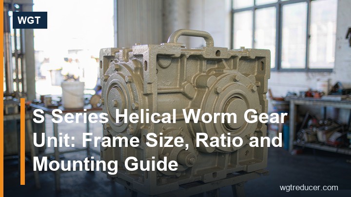
S Series Helical Worm Gear Unit: Frame Size, Ratio and Mounting Guide
An S series helical worm gear unit is a two-stage right-angle reducer that pairs a helical gear set with a worm gear set, and it earns its place on packaging lines, water treatment skids and light material-handling drives where a single-stage worm box cannot deliver the ratio and a full bevel-helical unit is more than the duty needs. This guide walks through what the series actually is, how the frame sizes from 37 to 107 differ, which mounting variant fits which machine layout, and a six-step sizing method you can apply to your own duty point.
What the S Series Actually Is
Inside the housing the power flows through two stages. The motor drives a helical pinion, which meshes with a helical gear; the helical gear shares a shaft with the worm, and the worm drives the worm wheel that carries the output. Because the worm stage turns the axis by 90 degrees, the whole unit is a right-angle drive, but the first helical stage does more than fill space — it lets the overall ratio build up in two steps, so the worm can run at a moderate single-stage ratio instead of an extreme one.
That layout explains the series' character. A single-stage worm gearbox tops out practically around 60:1 to 70:1 and loses efficiency quickly as the ratio climbs. A helical-worm unit reaches ratios from roughly 7:1 up to nearly 300:1 while keeping the worm stage in its comfortable range, which is why the S series helical worm gear unit shows up wherever slow output speeds and compact right-angle packaging meet — dosing conveyors, stirrers, gate drives, rotary tables.
Why the Helical-Worm Combination Earns Its Keep
The obvious question is why not just buy a bigger worm gearbox. Three reasons, all of them visible in the numbers:
- Efficiency at high ratio. Worm stage efficiency drops as ratio rises, because the lead angle of the thread shrinks. By pushing part of the total ratio into the helical stage, the worm thread stays coarser and the whole unit runs cooler at the same output speed.
- Torque density. The helical stage carries the first, fastest multiplication with much higher efficiency than a worm would, so more of the motor's power survives to the output. At a total ratio of 50:1 the difference against a pure-worm equivalent is commonly 10–20 percentage points of efficiency.
- Standard motor interface. The helical input stage gives the IEC motor flange a natural home, so the same frame accepts motors from small fractions of a kilowatt up to tens of kilowatts without changing the gearbox.
The trade-offs are equally real: the unit is longer than a single-stage worm box (two stages in one housing), it is not self-locking in most ratios, and it costs more than a worm-only box of the same centre distance. Whether those matter depends on the machine — a gate drive that must not back-drive needs a brake on the motor, not a hope.
Frame Sizes 37 to 107: What Changes Between Them
The number in the designation is the frame size, and it scales everything at once: centre distance of the worm stage, housing strength, allowable output torque and the motor sizes that can bolt on. Frame 37 is a small packaging-machine drive; frame 107 is a unit for heavy conveyors, mixers and rotary kilns.
| Frame | Typical ratio band | Typical motor range | Character of the duty |
|---|---|---|---|
| S37–S47 | 7 – 200 | 0.18 – 2.2 kW | Packaging, dosing, small gates |
| S57–S67 | 7 – 200 | 0.37 – 5.5 kW | Light conveyors, stirrers, turntables |
| S77–S87 | 7 – 250 | 1.1 – 11 kW | Belt conveyors, agitators, saws |
| S97 | 7 – 250 | 3 – 18.5 kW | Heavier conveyors, mixers, screens |
| SA107 | 7 – 300 | 5.5 – 45 kW | Heavy conveyors, kilns, thickener drives |
Treat the table as orientation, not a selection: the rated torque of each frame depends on the exact ratio, and a frame that is comfortable at i = 20 may be undersized at i = 100 for the same motor. The engineering data sheet for each frame (for example the SA107 hollow shaft unit) lists rated output torque per ratio, and that number — not the frame size — is what the sizing calculation must clear.
Ratios and Output Speeds in Practice
The ratio is the product of the two stages, and catalogues offer it in discrete steps because the helical and worm stages are each built from a fixed set of gear pairs. In practice that means you rarely get exactly 40.0:1 — you get 39.7 or 41.3 — and the output speed moves accordingly.
The working method is simple:
- Take the required output speed of the machine, say 28 rpm.
- Divide the four-pole motor speed (1440–1460 rpm) by it: 1450 / 28 ≈ 52.
- Pick the nearest available ratio step, here i = 53 or i = 55.
- Recalculate the true output speed: 1450 / 53 ≈ 27.4 rpm.
- Confirm the machine tolerates that speed; if not, adjust with a variable-frequency drive.
Two cautions. First, at ratios above roughly 80:1 the worm stage alone carries a very fine thread, and efficiency falls — if the duty allows, consider whether the machine can run at a higher speed with more torque, or whether a helical-bevel unit would suit better. Second, output torque scales with ratio for a given motor, but the frame's rated torque does not grow forever: large ratios on a small frame quickly hit the torque ceiling of the worm wheel, which is why the low-ratio and high-ratio ends of every frame's table have different limits.
Mounting Variants: S, SA, SAF, SAT and SAZ
The same gear set ships in several mounting configurations, and choosing the right one is as important as choosing the frame. In the common Chinese-series nomenclature used across this product family:
| Variant | Output | Mounting | Typical use |
|---|---|---|---|
| S | Solid shaft | Foot mounted | General machines with a coupling on the output |
| SA | Hollow shaft | Shrink disc or key on a shaft | Drives that hang on the machine shaft |
| SAF | Solid shaft | Foot mounted, reinforced base | Heavier foot-mounted drives |
| SAT | Hollow shaft | Torque arm | Shaft-mounted conveyors and similar |
| SAZ | Hollow shaft | Vertical flange | Vertical or flange-mounted assemblies |
The foot-mounted S and SAF variants suit machines where the gearbox sits on its own base plate and couples to the driven shaft. The hollow-shaft SA and SAT variants remove the coupling entirely: the gearbox slides onto the driven shaft and the torque reacts through the housing or a torque arm, which shortens the drive line and removes one alignment operation. A worked example of the hollow-shaft option is the S series hollow shaft range on our product pages, and for foot-mounted duty the S37 helical worm gear reducer page shows the classic base-mounted layout.
Sizing an S Series Helical Worm Gear Unit in Six Steps
A defensible selection takes six steps, in this order:
- Write down the duty torque. From the machine data: torque at the driven shaft, or power and speed if torque is unknown (T = 9550 × P / n).
- Apply the service factor. Uniform loads 1.0–1.25, moderate shock 1.25–1.5, heavy shock 1.5–2.0, jam-prone duties above 2.0. Multiply the duty torque by it.
- Fix the ratio from motor speed and required output speed, rounding to the nearest catalogue step.
- Choose the frame whose rated torque at that ratio exceeds the factored duty torque. If the marginal frame also runs at high ambient temperature or frequent starts, move one frame up.
- Choose the mounting variant (S/SA/SAF/SAT/SAZ) from the machine layout, and fix the output shaft or bore dimensions.
- Check the thermal side. Continuous duty at high input speed or high ambient temperature may need a fan, a larger frame, or a lower duty cycle — worm stages reject heat through the housing surface, and that surface scales with the frame, not the torque rating.
Steps 1 to 4 can be done in minutes with the online selection system, which filters the range by torque, ratio and mounting and returns the frames that survive all constraints.
Thermal Capacity: The Quiet Limit of Worm Stages
Worm gearboxes fail thermally long before they fail mechanically, and the S series is no exception. The worm stage converts a few percent of transmitted power into heat, and the housing must reject that heat to the air. Three practical consequences:
- Ambient temperature matters. A unit selected at 20 °C may overheat at 45 °C in a plant room, because the temperature rise adds to the ambient.
- Input speed matters. Higher motor speed churns more oil and generates more friction heat at the same torque, so the same gearbox has a lower continuous torque rating at 1450 rpm than at 960 rpm.
- Duty cycle helps. An intermittently running drive can be sized smaller than a continuously running one at the same peak torque, because the housing cools between runs.
If the duty point sits near the thermal limit, the standard fixes are, in order of cost: improve ventilation around the housing, fit a cooling fan on the input, step up one frame size, or move to a helical-bevel unit whose efficiency wastes less power in the first place.
Frequently Asked Questions
What is the difference between the S series and a pure worm gearbox?
The S series has a helical first stage in front of the worm stage, so it reaches higher total ratios with better efficiency and a stronger output bearing arrangement. A pure worm gearbox is shorter and cheaper but loses efficiency quickly above ratios of about 40:1 and is often self-locking — which is an advantage only when back-driving must be prevented.
Is the S series self-locking?
Generally no. The helical first stage back-drives easily and keeps the worm stage out of its self-locking ratio region for most catalogue combinations. If the application must not back-drive — vertical gates, hoists — fit a motor brake or a holding device; never rely on the gearbox for holding.
Can the S series run with the output shaft upward or in any mounting position?
Mounting position affects oil distribution and the position of the breather and drain plugs. Standard units are filled for a specified mounting position; other positions are possible but need the correct oil level and plug arrangement confirmed before delivery. Always state the intended mounting position in the enquiry.
How do I replace an old S series unit without redesigning the machine?
Record the nameplate (frame, ratio, mounting variant, motor size) and measure the output shaft diameter and the motor flange. The series' frame dimensions follow a stable convention, so a like-for-like frame usually bolts straight in; our replacement guide walks through the nameplate reading step by step.
If you have a duty point in hand, the fastest route from torque and speed to a concrete frame is the online parametric selection tool — it applies the service factor and ratio logic above automatically. For quotations, drawings or cross-checking an existing installation, contact our engineering team with the nameplate data and the driven machine description.
