


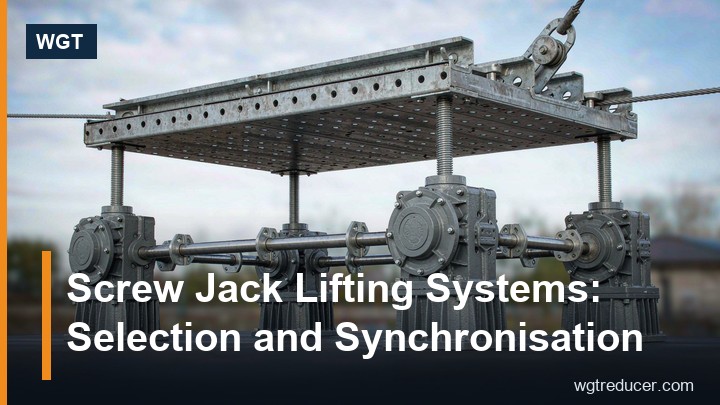
Screw Jack Lifting Systems: Selection and Synchronisation
Screw Jack Lifting Systems: Selection and Multi-Unit Synchronisation
A screw jack lifting system is chosen in two steps, and most problems come from skipping the first: size each jack against the load it really carries, then decide how the jacks are held level with one another. This guide covers both — load, travel and speed for a single jack, and shaft, motor or platform for a bank of two to four.
What a worm gear screw jack does that a hydraulic cylinder does not
A worm gear screw jack turns motor torque into linear thrust through a trapezoidal lifting screw driven by a worm and worm wheel. Three mechanical properties decide where it fits:
- It holds load mechanically. The worm reduction can act as a brake when thread geometry and friction allow it, so a raised load stays raised after the motor stops — no pump pressure or check valve involved.
- It positions repeatably. Travel is set by counting screw revolutions, so height is repeatable without a proportional valve.
- It is limited by buckling and nut wear, not by oil. A screw loaded in compression can buckle if its free length is too long, and the nut face wears with load and travel.
The design is covered in the JWM and SWL series worm screw jacks range.
Translating versus rotating screw: fix the direction of motion first
Before any number is entered, decide which part moves. This choice changes the mounting, the bearing loads and often the price.
| Configuration | What moves | Typical use | Mounting note |
|---|---|---|---|
| Translating screw | The screw travels; nut fixed in the body | Platform lift, hatch, adjustable stand | Screw end needs a load pad; check buckling length |
| Rotating screw | Screw turns in place; a travelling nut moves | Load travels through a structure | Screw supported both ends, guided against rotation |
| Translating nut | Nut travels on a fixed rotating screw | Long travel in a narrow space | Cleanest buckling case; screw bearings take full thrust |
| Anti-backlash twin nut | Nut travels with a preloaded second nut | Positioning where reversal play matters | Preload raises friction and motor torque |
If the load must never drift after power-off, treat self-locking as a property to be confirmed for the exact model and lubricant, not a guarantee of a series name.
Sizing one jack: the four numbers you actually need
- Load per jack. Divide the lifted mass plus the platform the jacks carry by the number of jacks, then apply a service factor for shock, off-centre loading and duty. A jack that adjusts a stand occasionally and one lifting the same mass several times an hour are different applications.
- Travel. Working stroke plus margin at both ends for limit switches. Travel is not free: it sets screw length, which sets the buckling limit for compression-loaded screws.
- Lifting speed. Set by the process. Speed follows from motor speed, worm ratio and screw lead, so working back from required speed and load is the quickest route into the catalogue.
- Duty and environment. Starts per hour, temperature, dust, washdown and outdoor exposure decide protection class, lubricant and whether the screw needs a bellows.
A jack overloaded in thrust is rarely what stops a machine. Side load on an unguided screw, or limit switches wired to the wrong direction, are the commoner failures.
Speed, ratio and the worm reduction
Output thrust is input torque multiplied by ratio, screw lead and worm-stage efficiency; output speed is input speed divided by ratio, multiplied by lead. Low speed buys thrust: a high ratio moves the load slowly on the same motor, so a fast process needs a larger frame or motor. Raising is harder than lowering, so check the motor and brake on the lowering stroke separately if the load must stop there. And because the worm stage slides rather than rolls, duty cycle — not only thrust — decides whether a standard unit is suitable.
Multi-unit synchronisation: three ways to keep jacks level
Two or more jacks under one platform add a failure mode: uneven travel racks the platform and puts jacks in torsion they were not designed for. Three methods are in practical use.
| Method | How it works | Accuracy | Best for | Weak point |
|---|---|---|---|---|
| Mechanical link shaft | One motor drives a line shaft through bevel boxes to each jack | Highest — set by gearing and backlash | Heavy platforms, critical levelling | Layout must allow a straight run |
| Two-motor electrical coupling | Master and follower motors with position feedback | Good — limited by sensor and drive response | Layouts where a shaft cannot be routed | Needs feedback and a synchronisation controller |
| Independent jacks, rigid platform | Each jack driven separately | Lowest — the platform carries the error | Slow, non-critical levelling | Platform and mounts absorb misalignment |
Where the platform is long — a multiple-point press bed, a stage lift, a wide hatch frame — the line shaft is normally the simplest robust answer, because synchronisation comes from geometry rather than control. Where a shaft is impossible, coupled motors need position feedback on every jack; lose one encoder and the platform leaves level.
Three mechanical points apply to every method:
- One jack must float in the horizontal plane, so thermal growth and fabrication tolerance do not load the screws sideways.
- Vertical guides take the horizontal load — two at minimum — so the screws never act as guides.
- Limit switches are wired per motion, not per jack, so one jack reaching its end stops the whole group.
Mounting and maintenance points that get missed
- Support the screw. Check a compression-loaded screw for buckling over its free length and guide its end with the load pad.
- Protect the thread. Grit on an exposed trapezoidal screw acts as grinding paste; a bellows costs far less than a screw and nut.
- Lubricate the nut as well as the worm stage — it is the part most often forgotten.
When a screw jack is the wrong answer
A screw jack fits poorly when travel is long, speed is high, duty is continuous, or the screw would work in heavy contamination; a hydraulic cylinder, chain hoist or rack and pinion is then the better choice. It is strongest where the job is precise, slow, self-holding and intermittent.
For rotational duty the same worm-reduction logic applies and the WP series worm gearbox is the closer starting point. Where a jack is motor-driven, check the SWL worm gear screw jack drive against your thrust and travel, and the couplings range for the jack-to-shaft connection.
Get advice from WGT
Send the load per jack, the travel, the lifting speed, the number of jacks and your preferred synchronisation method through our contact page. We will confirm a jack model, the screw configuration and the drive arrangement, with a drawing and a factory delivery date.
Frequently asked questions
How do I calculate how much load each jack carries?
Add the lifted mass to the weight of the platform and frame, divide by the number of jacks, then apply a service factor for duty and off-centre loading. Do not size on nominal load alone: a centre of gravity offset from the jack pattern loads the near jacks more.
Can two screw jacks be driven by one motor?
Yes, and it is the usual arrangement above two units. One motor drives a line shaft through bevel gear boxes to each jack, so all screws turn at the same speed and travel difference is set by gearing rather than control.
Do screw jacks hold the load when the motor stops?
In many worm-drive configurations the reduction prevents the screw from turning back, so the load stays where it was left without a brake. This depends on thread geometry, ratio and the friction of the specific unit, so confirm it for your model and condition.
Related reading
- How a worm gear reducer works — the reduction principle behind every worm screw jack, and the frames you can check in the WGT online selection tool.
