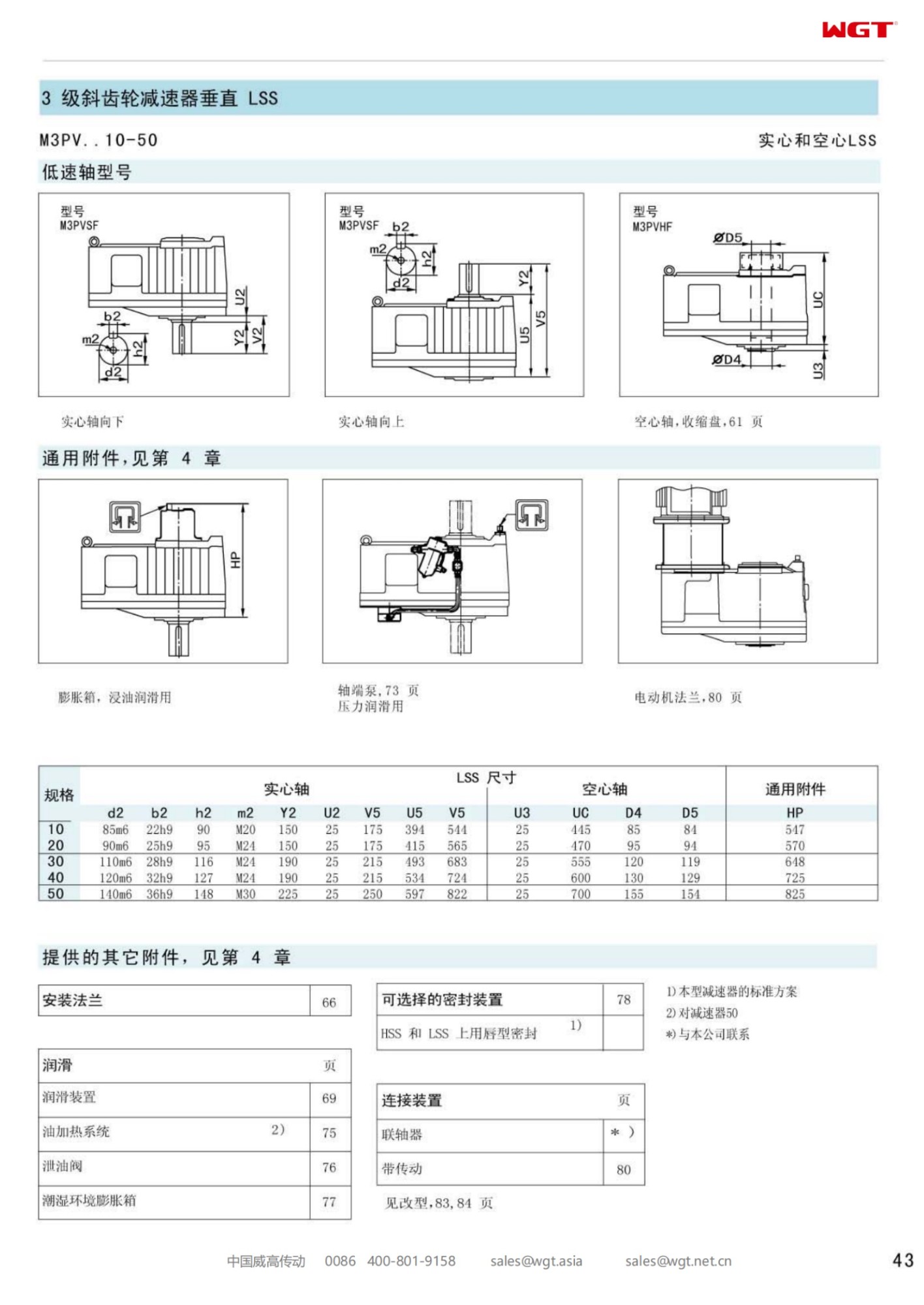
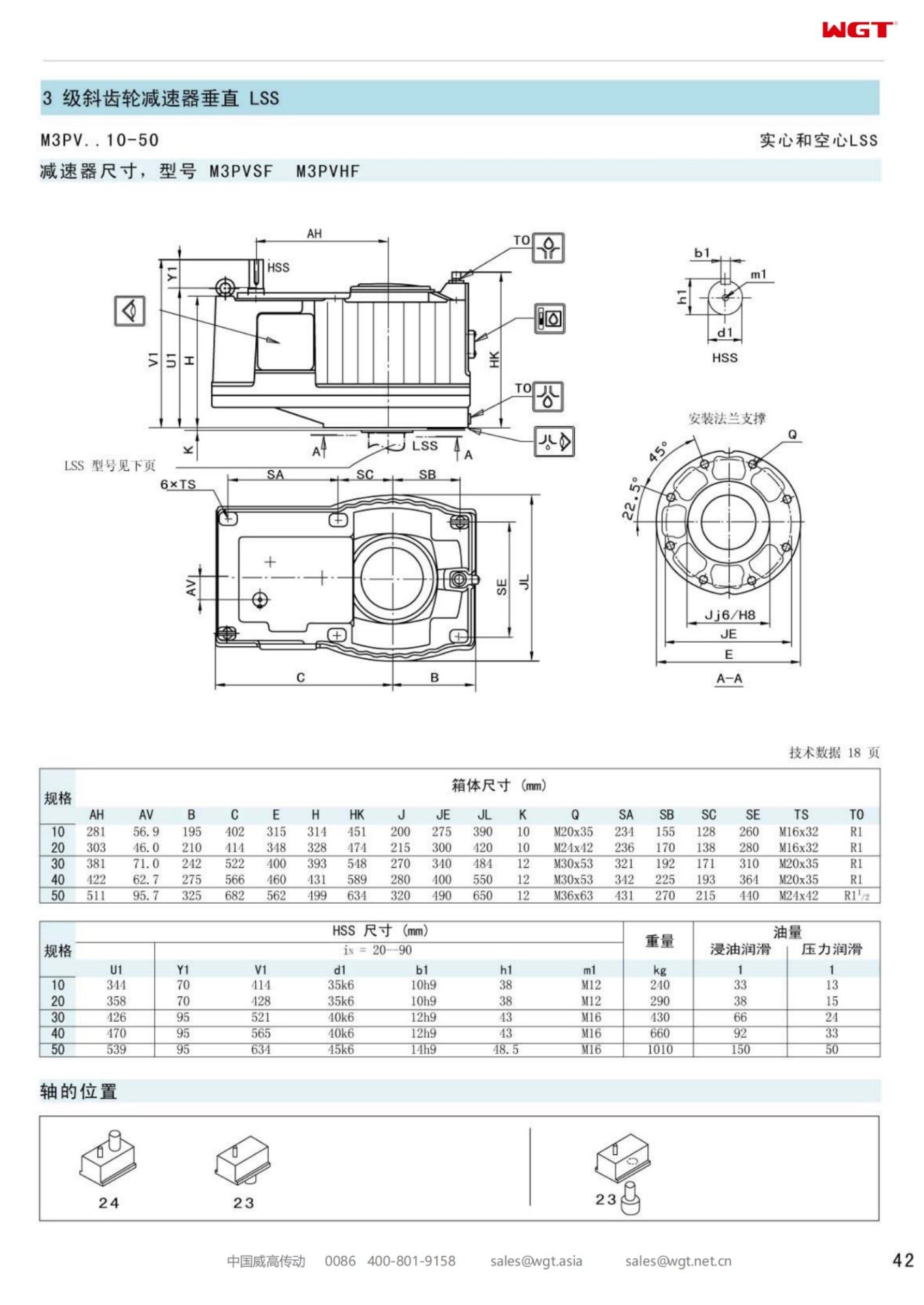
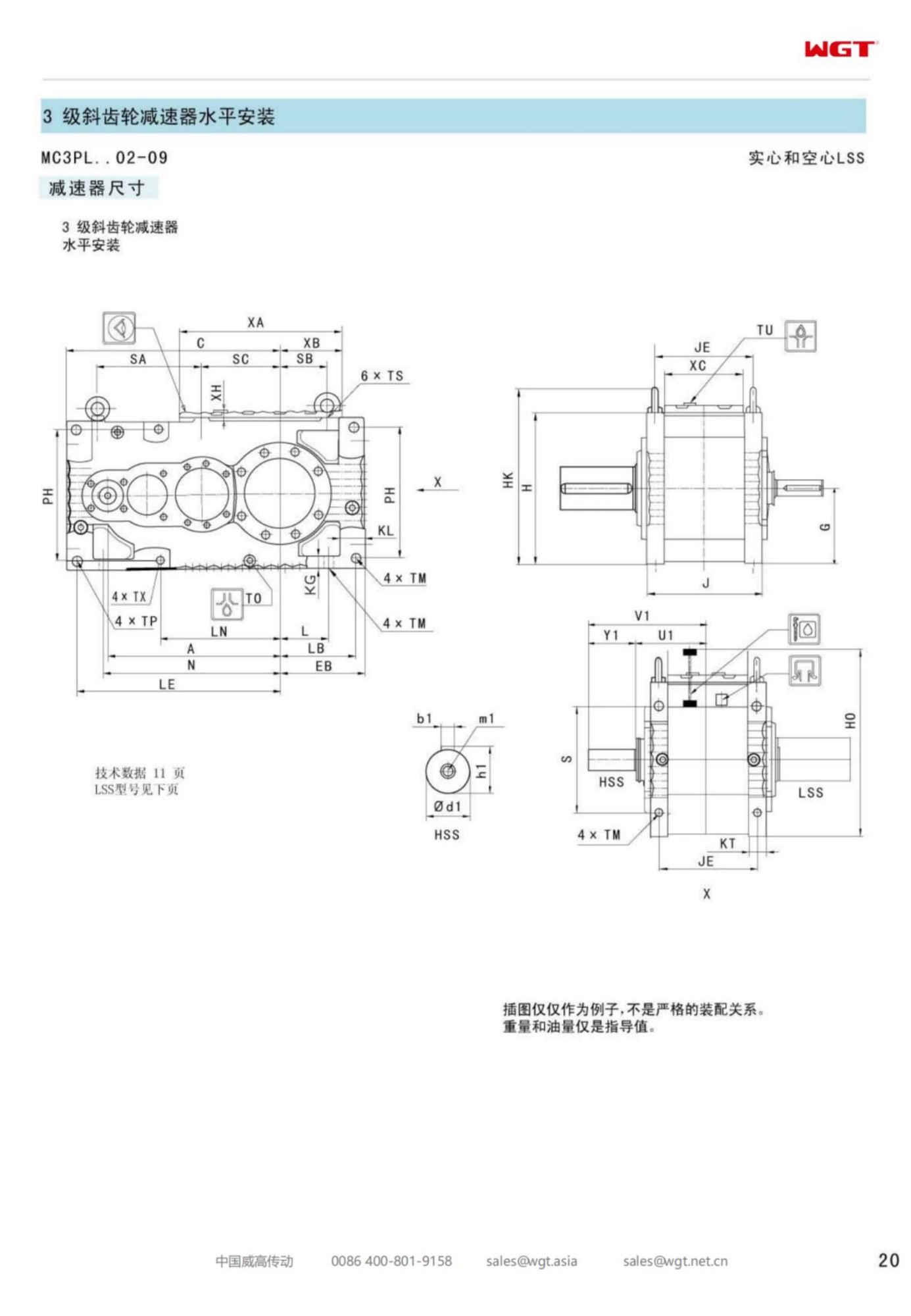
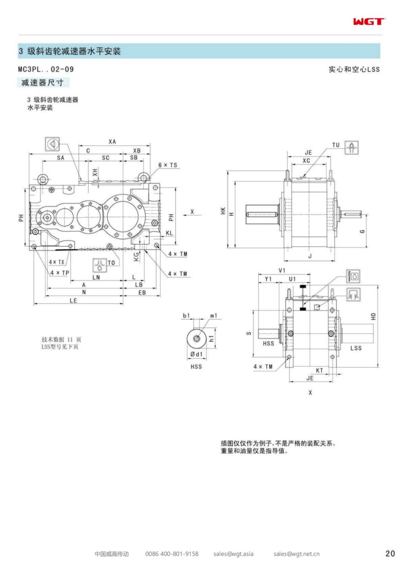
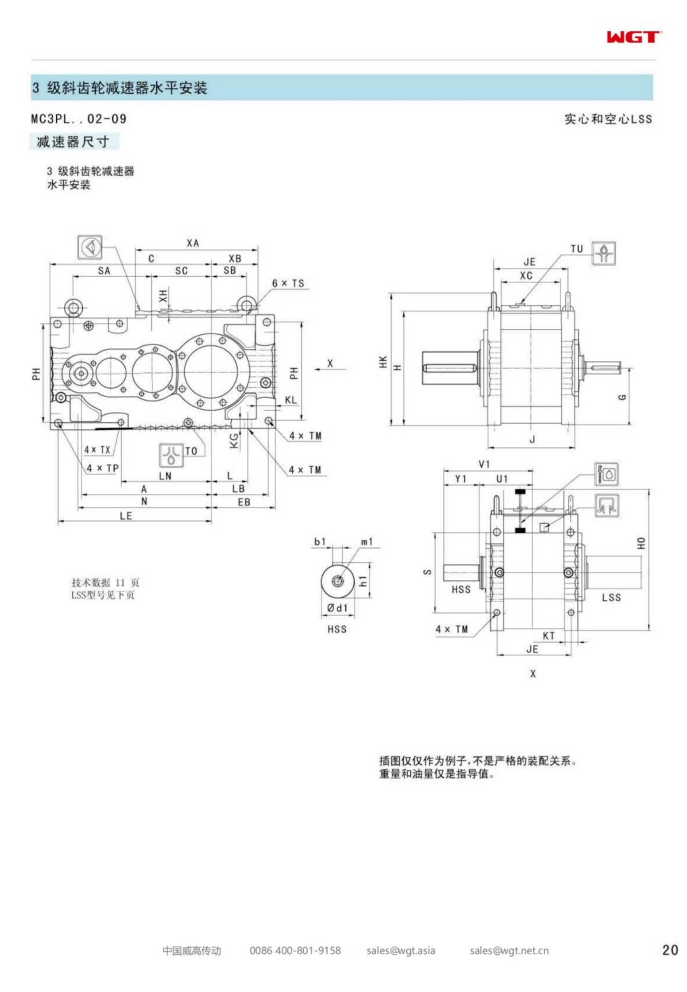
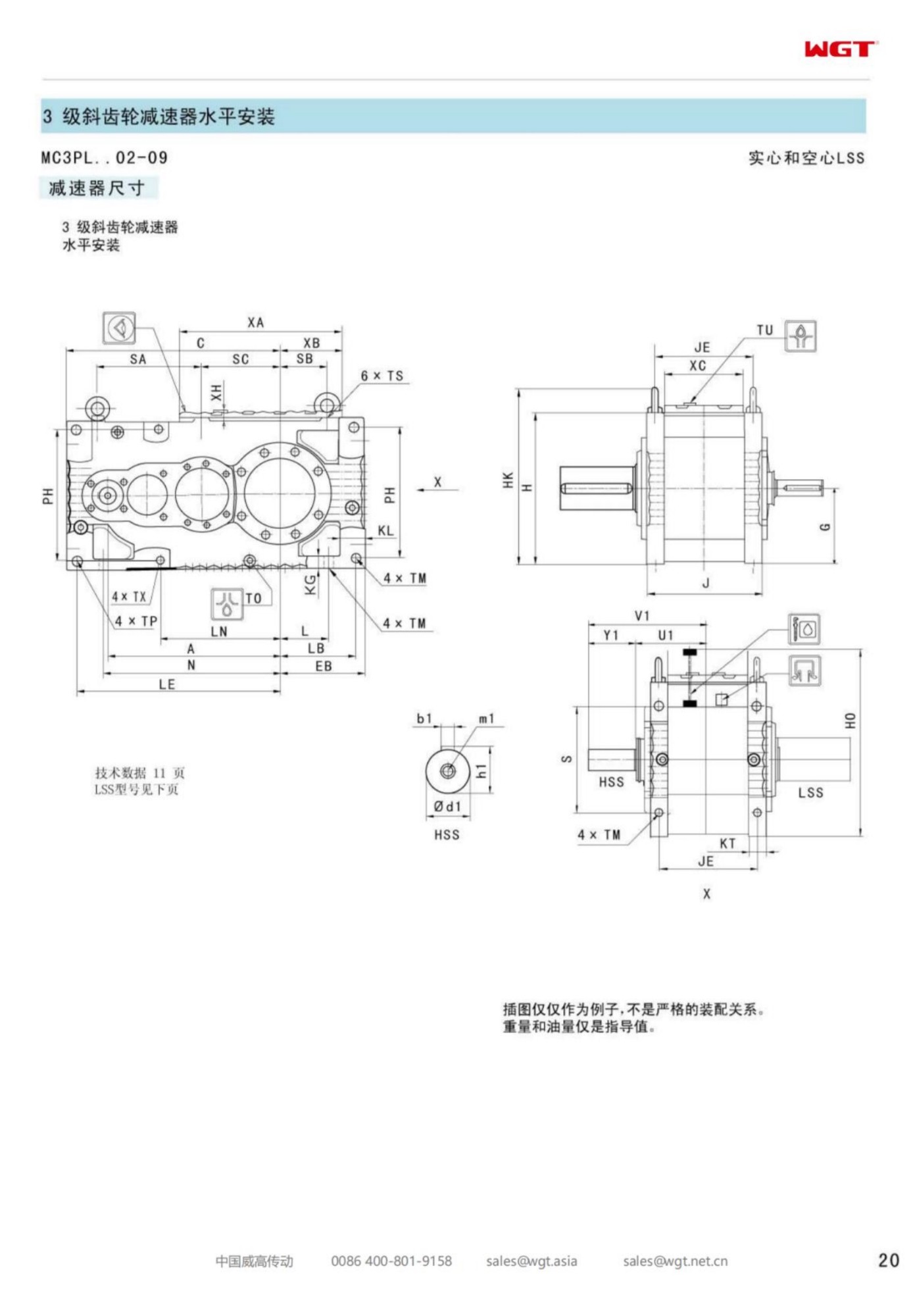
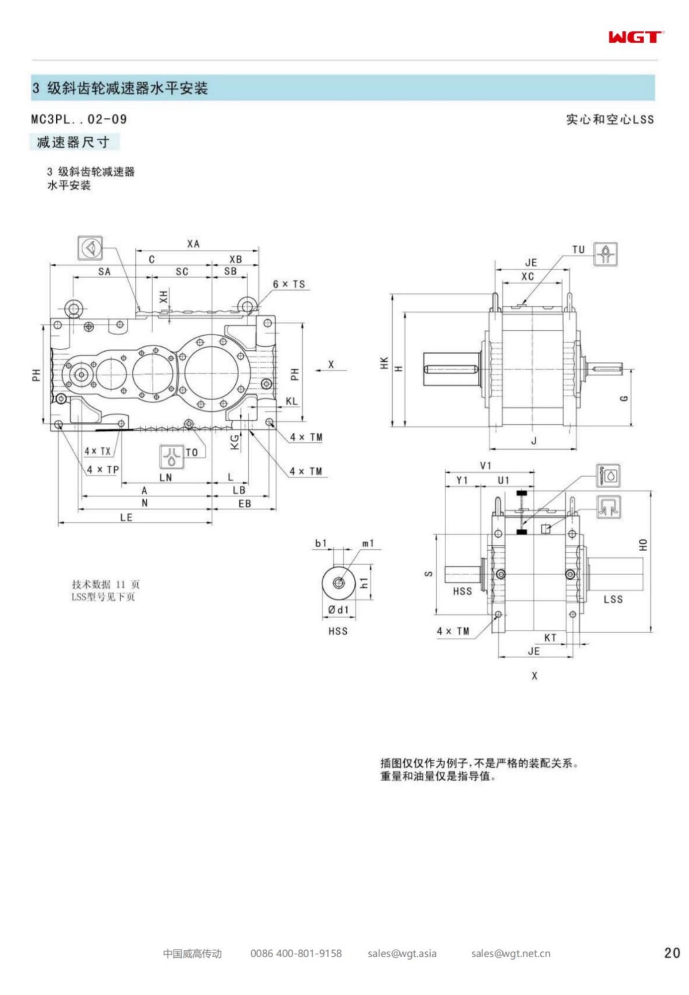
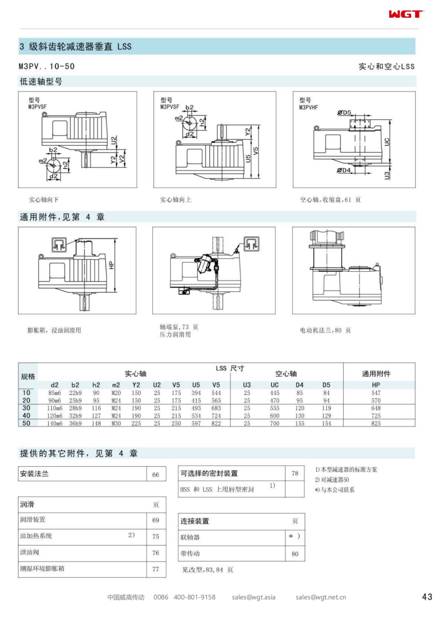
The M3PVHF50 vertical hollow shaft gear unit takes the size 50 vertical parallel-shaft frame and bores the output straight through, so the driven shaft passes up into the unit and out the top. On a top-entry agitator, a vertical pump or a cooling tower fan, that single change removes a coupling, a bearing housing and the alignment work between them - the process shaft becomes the gear unit output shaft. For plant layouts where headroom above the vessel is tight, it is often the only arrangement that fits at all.
How a Through Bore Changes the Installation
With a solid output shaft the driven shaft has to be coupled to it, which means two bearing systems that must be aligned to each other and kept aligned as the structure moves. With a hollow bore the gear unit output bearing supports the process shaft directly; the shaft is keyed or clamped inside the bore and the unit carries the radial and thrust loads that the old separate bearing housing used to take. The result is a shorter stack above the tank, fewer parts to align, and one less lubrication point in the plant.
Reading the Designation Letter by Letter
| M | Three-stage industrial gear unit family |
| P | Parallel-shaft helical gearing; not a right-angle frame |
| V | Vertical axis, output facing down into the vessel |
| H | Hollow output shaft, bored for the process shaft |
| F | Foot and flange mounting on the vessel head or a steel frame |
| 50 | Frame size, the entry size of the vertical range |
What the Frame Size Means in Service
Frame size is a statement about gear centres, shaft sections and bearing envelope rather than about a single torque figure. At size 50 the unit suits medium agitators, tower fans and vertical elevators; a heavier vessel or a taller column of liquid moves the requirement up the range. Because the process shaft is carried by the unit, the deciding numbers are usually the shaft diameter the bore must accept and the combined radial and axial load the impeller puts on it, not the nominal output torque alone.
Machine groups this unit is specified into: Top-entry agitators driven through a hollow hub Vertical pumps with a keyed shaft through the gear unit Fan stacks where the impeller shaft passes straight through Silo stirrers and dischargers with an internal centre shaft Vertical screw conveyors with an extended through shaft Basin flocculators driven from a bridge-mounted headstock Rising-shaft mixers on crystalliser trains Vertical bucket elevators with a keyed boot shaft
Mounting and Oil Considerations for a Hollow Vertical Unit
A hollow vertical unit is normally bolted to a machined flange on the vessel top or to a fabricated steel headplate, and that face has to be flat to within a fine tolerance or the bore will not align with the process shaft. The output seal arrangement matters more here than on a horizontal frame, because the seal sits directly above the product: a dry-running lip seal with a dust lip is a different selection from one wetted by splash or vapour. Oil level is checked at the specified standstill position, and the breather must be fitted at the point marked for the vertical posture - a unit commissioned with a horizontal-position breather will weep oil.
Information Needed for a Firm Offer
To size a hollow vertical frame properly we need the process shaft diameter and keyway, the axial load direction, the shaft speed and the ratio required, plus the mounting face drawing. Ambient temperature, duty cycle and whether the drive starts loaded all affect the oil and bearing choice. The online selection system accepts these values directly, and a written proposal with drawings follows.
The M3 Series at a Glance
| Model | Centre distance | Output | Typical duty |
|---|
| M3PSF50 | size 50 | solid shaft, foot | conveyors, feeders |
| M3PSF60 | size 60 | solid shaft, foot | crushers, mixers |
| M3PSF70 | size 70 | solid shaft, foot | ball mills, shredders |
| M3PSF80 | size 80 | solid shaft, foot | kilns, heavy conveyors |
| M3PSF90 | size 90 | solid shaft, foot | mill and kiln drives |
| M3RSF50 | size 50 | solid shaft, foot, right-angle | inclined conveyors, elevators |
| M3RSF60 | size 60 | solid shaft, foot, right-angle | screw classifiers, feeders |
| M3RHF70 | size 70 | hollow shaft, foot, right-angle | agitators, drum drives |
| M3PHT80 | size 80 | hollow shaft, torque arm, parallel | shaft-mounted conveyors |
| M3RHT90 | size 90 | hollow shaft, torque arm, right-angle | heavy shaft-mounted drives |
All frames in the table belong to one industrial family. P = helical parallel-shaft, R = bevel-helical right-angle; the low-speed shaft is solid (S) or hollow (H), mounted on feet (F) or a torque arm (T).
Selection Example: Cooling tower fan stack drive
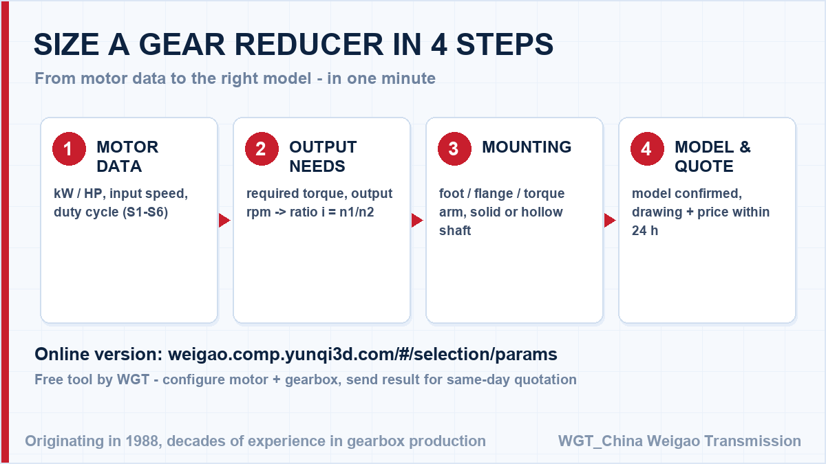
Take a 30 kW motor at 1470 rpm turning a fan shaft at 32 rpm. The ratio follows directly: 1470 / 32 = 45.9, so a ratio near i=46 is selected and the bore is sized to the fan shaft diameter. In this case the hollow output bore takes the fan shaft straight through the gear unit, which removes the coupling and the separate thrust bearing above the stack. That single division gives the catalogue ratio; the service factor for your duty class is then applied to the torque, and the frame size follows.
![how to size a industrial helical gearbox in four steps]()
Sizing flow: motor speed, target output speed, torque, service factor.
Where This Series Works in Practice
Overland conveyor system
A mining company drives a two-kilometre overland conveyor with heavy-duty helical gear units at the head station. Continuous 24-hour duty, frequent starts under full load and minimal maintenance windows were all part of the specification.
Cement plant bucket elevator
A cement works renewed the gear units on its bucket elevators during a kiln shutdown. The new units bolted onto the old foundations without modification, and the elevator was back in service within the planned window.
Technical Questions, Answered
What documentation comes with an industrial gear unit?
Every shipment carries an installation manual, a dimension drawing, the nameplate data and a bench test record covering noise, temperature rise and backlash. Material certificates for shafts and gearing are available on request.
How is the unit transported and lifted on site?
Units ship in export wooden crates with lifting points on the housing clearly marked. On site, lift only from these points with the specified slings - lifting from shafts or covers is expressly forbidden in the manual.
![industrial helical gear reducer application fields]()
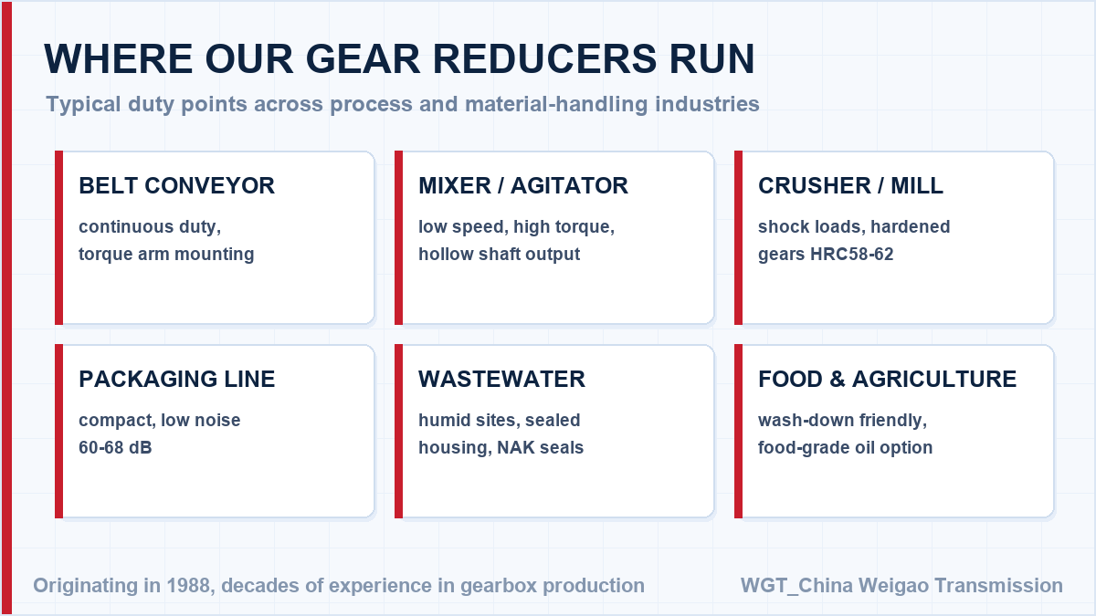
Common application areas for right-angle industrial helical drives.
Design Review, Datasheet and Price - Same Day
Planning a new machine? Skip the back-and-forth: configure your drive in the WGT Motor & Gearbox Online Selection System and send us the result for a same-day quotation.
Send the interface drawing or the frame dimensions you need to match, and we return a 2D drawing and 3D STEP model with the quotation, so your design review is not held up waiting on the supplier. Looking for a speed reducer for bucket elevator? Tell us the duty point and we will confirm the model in writing.