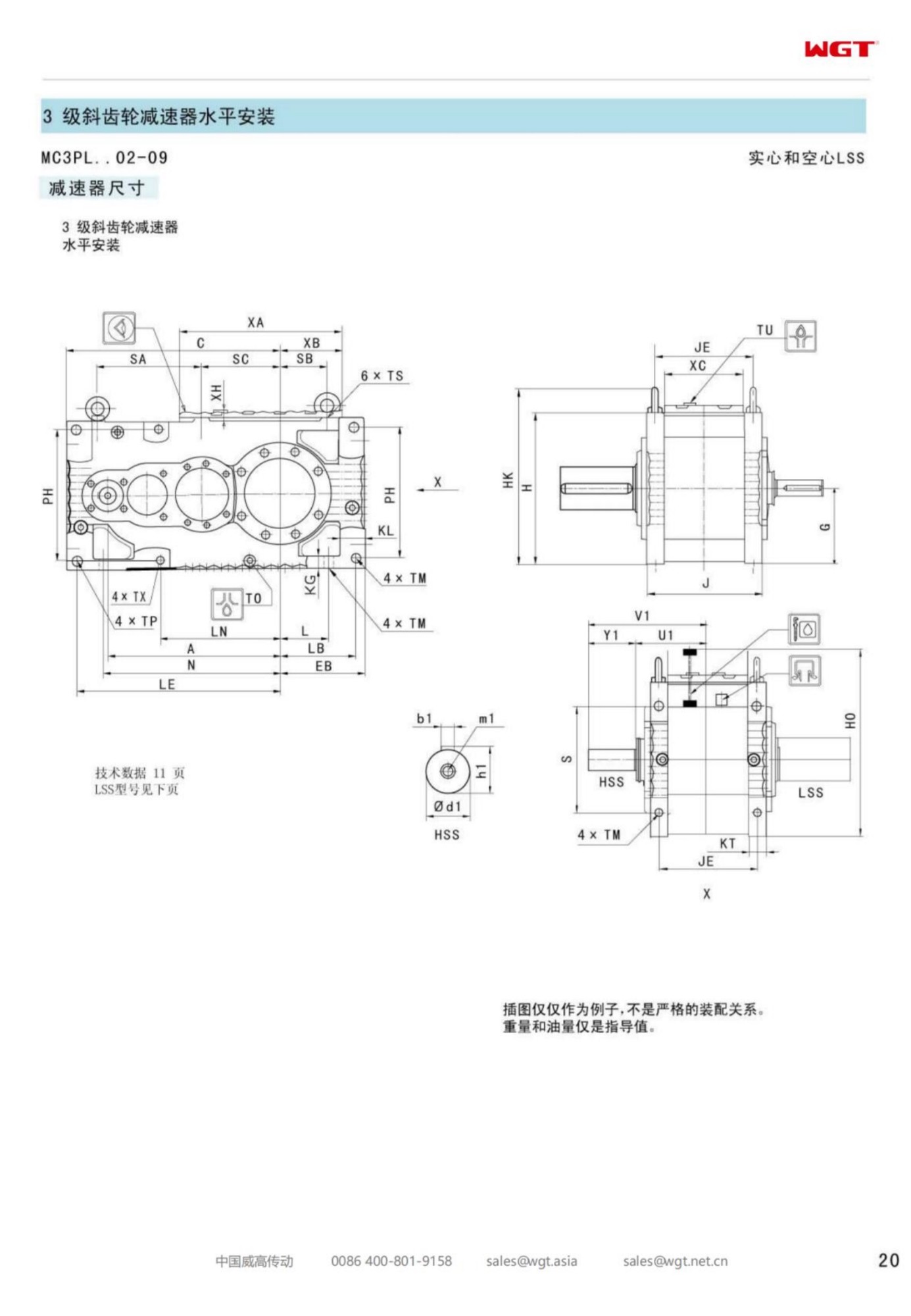
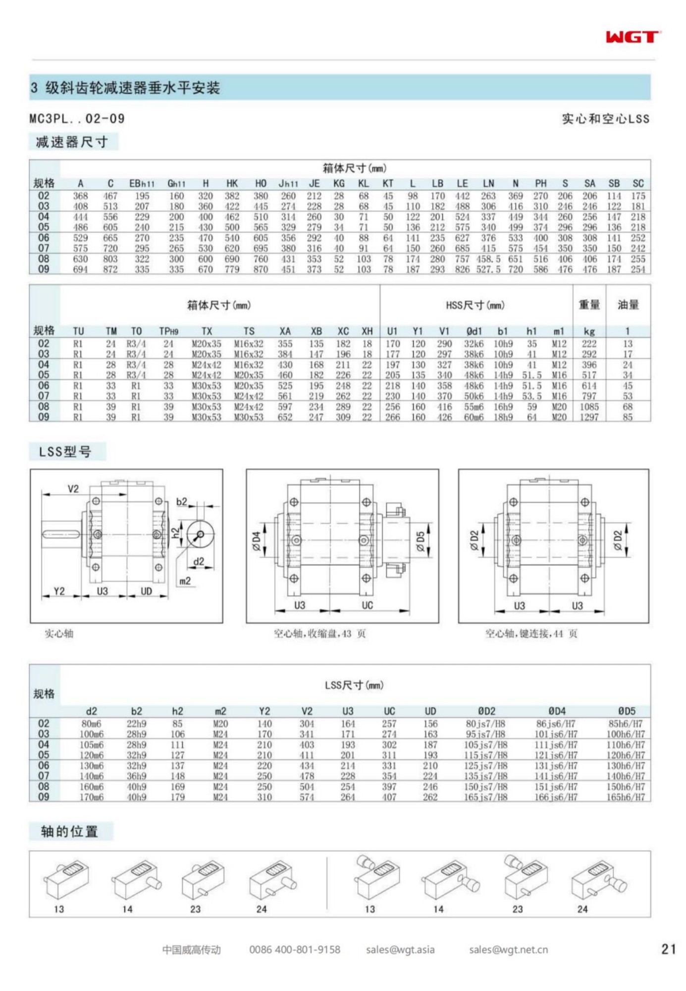
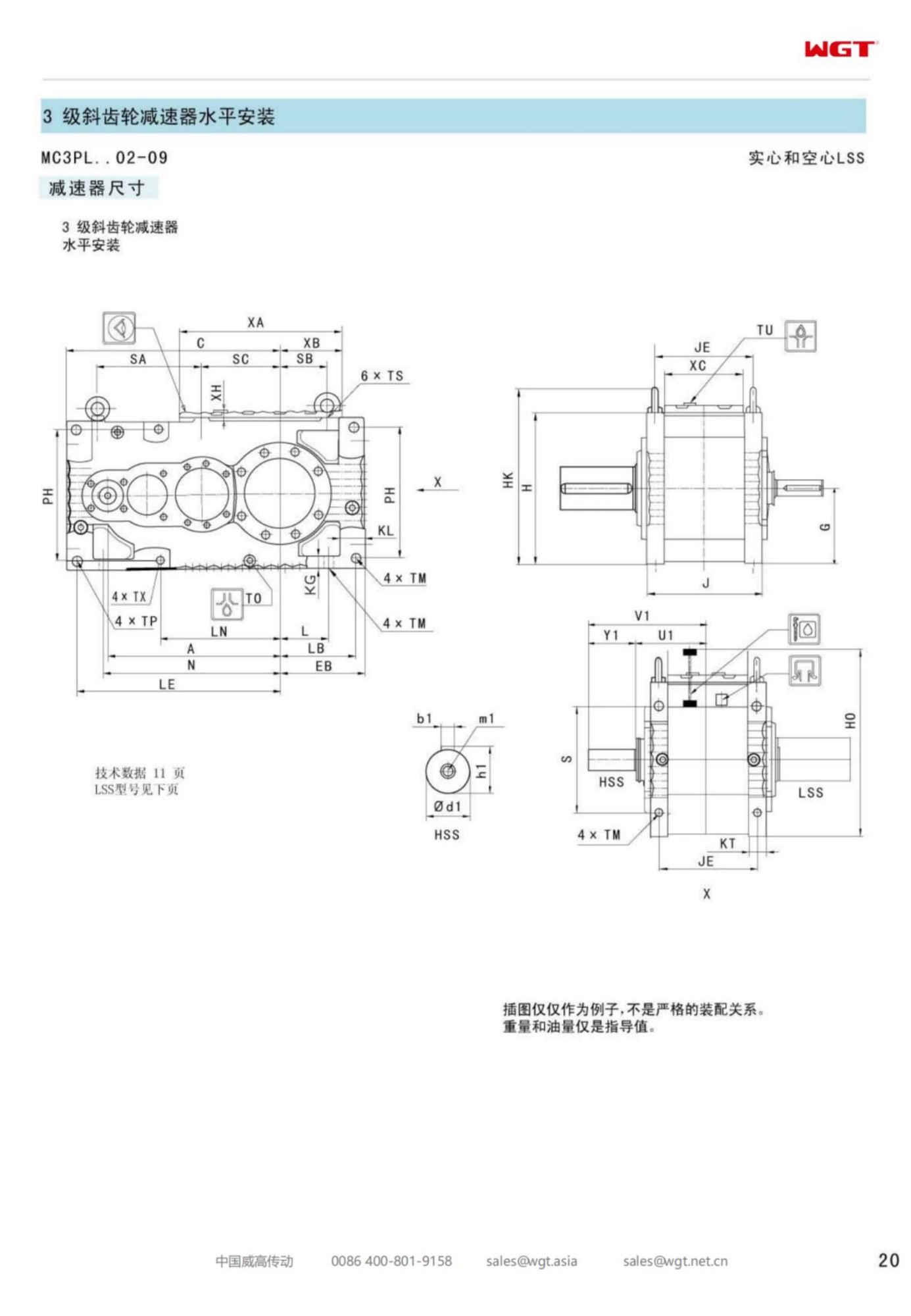
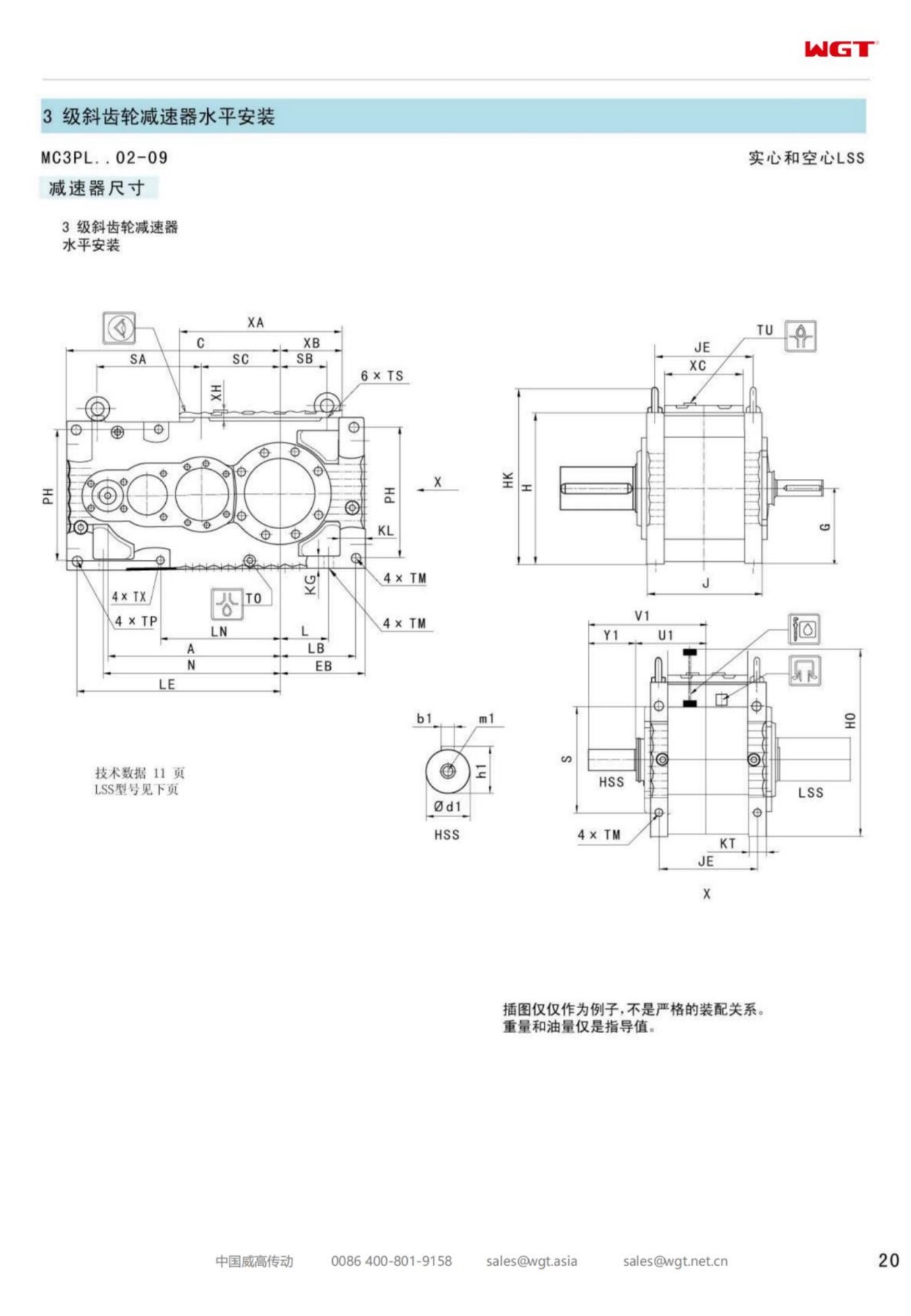
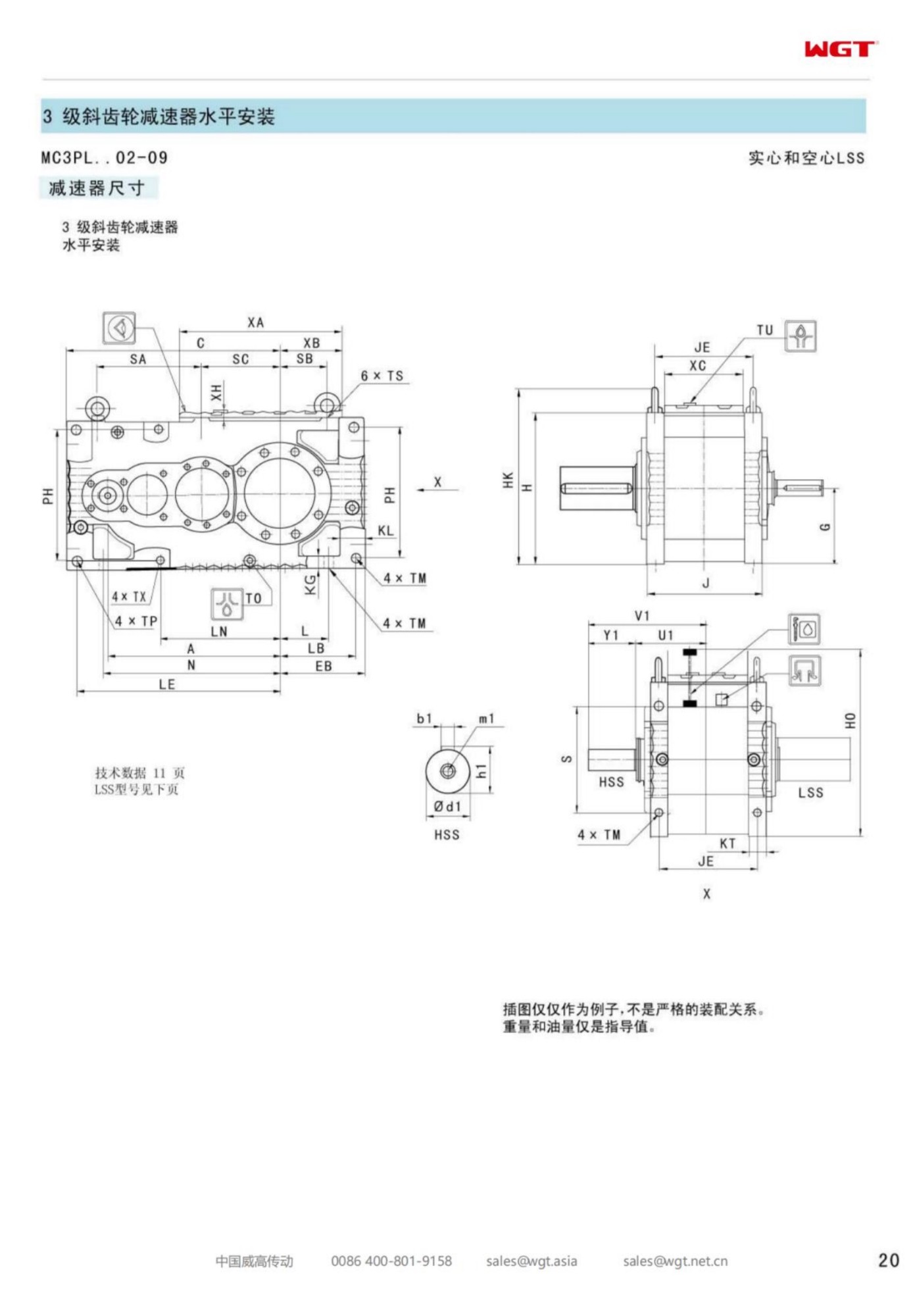
Phosphate moves as rock, as slurry and as dust, and the dust is the part that matters to a gearbox. The MC3PLST03 parallel shaft gear unit drives the conveyor that carries it: three helical stages, a solid output shaft onto the pulley, and a torque arm that puts the reaction into the conveyor stringer instead of into a foundation that was never poured.
What follows sets out the code, the torque-arm case, the sealing questions a fertiliser plant raises, and the numbers a buyer needs before asking for a price.
Phosphate Dust Finds Every Gap
Ground phosphate is fine, slightly hygroscopic and mildly acidic when it picks up moisture. It settles on everything, cakes where oil film catches it, and holds damp against painted steel. A drive in that atmosphere is judged by how well it keeps the dust out and how easily it sheds what lands on it.
Reading MC3PLST03
Four decisions are already encoded before the frame number.
| MC | Industrial gear unit family for continuous plant duty |
| 3 | Three stages of reduction in one housing |
| P | Parallel-shaft helical gearing, coaxial input and output |
| L | Level output axis into the pulley shaft |
| S | Solid output shaft, keyed to the pulley |
| T | Torque-arm reaction, no baseplate required |
| 03 | Third frame of the three-stage band |
So: three-stage industrial unit, parallel shafts, level axis, solid output, torque-arm mounting, third frame of the band. The frame number is the only variable a buyer usually has to weigh.
Torque Arm on a Conveyor Stringer
Conveyors in a fertiliser works are usually built on fabricated stringers, and nobody wants to cast a plinth under each drive. A torque arm bolts to that stringer, takes the reaction there, and lets the pulley shaft position the drive. Installation is a coupling, one bracket and a check of the arm angle - an hour's work rather than a day's.
Keyed Output Onto the Pulley Shaft
Conveyor head shafts are long, supported in plummer blocks, and already keyed for a coupling. A solid output meets that arrangement directly. Where a plant prefers to hang the drive on the pulley shaft itself, the hollow-bore models in the same family do that job; the choice is a layout decision, not a quality one.
Acid Mist and Fertiliser Plant Air
Around a phosphate plant the air carries a little of everything: ground rock, process vapour, and the fine mist that forms wherever acid is handled nearby. A paint system chosen for a dry industrial hall will not last in it. Specify the finish for the atmosphere, keep the breather out of the drift, and leave touch-up paint with the stores so a chip is dealt with in the week it happens.
Starting a Loaded Belt
A phosphate conveyor is often stopped loaded because the upstream unit tripped. Restarting it means breakaway torque on a full belt sitting on idlers that have settled into the material. That figure, not the running torque, is what the drive has to deliver, and it is the number the plant engineering team can supply from its own experience.
Sealing Against Dust and Damp
Two enemies meet at the output seal: abrasive powder outside and oil inside. A protected seal arrangement with a clean counterface on the shaft keeps the boundary where it belongs. A shaft that has been allowed to rust in storage will destroy a new seal in a month, so storage practice matters as much as the seal itself - keep the unit crated until it is lifted into place.
Three Stages on a Long Incline
Belt speeds on phosphate conveyors are modest and motor speeds are not, so the ratio lands in three-stage country. Three meshes let the case stay compact beside the pulley, which matters on an incline where the drive has to clear the belt line without eating into the walkway.
Shimming and the Arm Stop
The arm stop has to be set so the drive cannot rotate past its working angle in either direction, including during a stall or a reverse jog. Set it with the drive at rest, check it again at running torque, and leave a visible gap so the next fitter can see what correct looks like. On a vibrating stringer, that gap is the only reliable witness.
From Tonnage to Output Speed
Rated tonnage and belt speed set the pulley revolutions, the pulley diameter converts that to belt speed, and the motor speed divided by the pulley speed gives the ratio. Torque follows from the loaded-belt tension at the drive pulley, multiplied by the service factor the plant's own history supports. Then the frame is a lookup, not a guess.
The Enquiry for a Phosphate Line
Send the pulley shaft diameter and keyway, belt width and speed, tonnage and material bulk density, the motor frame and speed, the mounting steel available for the arm, and the atmospheric conditions - damp, acid mist, ambient range. A photograph of the existing drive position settles the rest in one look.
Frame Three in a Fertiliser Works
Frame three covers the conveyors that feed a phosphate plant's day: short transfers, incline sections and load-out belts where the torque is real but the case must stay out of the way. It is the smallest step above the compact frame, and on a works with dozens of conveyors it is the frame that gets repeated - which is a good reason to make sure its sealing and finish are right the first time.
Acid dust, a loaded belt and a stringer for a bracket - three stages carry the load:
- Phosphate rock conveyor at a fertiliser works
- Ground rock transfer belt in a milling plant
- Phosphate load-out conveyor at a port terminal
- Reclaim belt under a phosphate stockpile
- Incline conveyor from a rock crusher
- Blending plant feed conveyor
How Customers Use This Unit
Coal handling conveyor
A power station coal-handling plant standardized on one industrial gear family for thirty drives. A single spare-part pool now covers the whole conveyor network, from transfer points to the bunker feed.
Dredger pump drive
A dredging contractor powers its slurry pump skid with an industrial gear unit built for shock loads. The dense abrasive mixture demands a rigid drive train, and ground gearing has kept backlash unchanged over multiple seasons.
What Engineers Ask Us
How do I install the unit on an inclined conveyor?
Mount the unit with the output shaft horizontal or as recommended for your mounting position, and choose the anti-run-back option so the loaded belt cannot drive the gearbox backwards when power is cut. Tell us the incline angle when you order.
What is the difference between a keyed hollow shaft and a shrink-disc connection?
A keyed hollow shaft is the economical choice for normal torque and easy maintenance. A shrink-disc connection transmits higher torque with zero backlash and no keyway wear, and is preferred for reversing or high-torque duties.
Model Table: Frames, Shafts and Duty
| Model | Centre distance | Output | Typical duty |
|---|
| M3PSF50 | size 50 | solid shaft, foot | conveyors, feeders |
| M3PSF60 | size 60 | solid shaft, foot | crushers, mixers |
| M3PSF70 | size 70 | solid shaft, foot | ball mills, shredders |
| M3PSF80 | size 80 | solid shaft, foot | kilns, heavy conveyors |
| M3PSF90 | size 90 | solid shaft, foot | mill and kiln drives |
| M3RSF50 | size 50 | solid shaft, foot, right-angle | inclined conveyors, elevators |
| M3RSF60 | size 60 | solid shaft, foot, right-angle | screw classifiers, feeders |
| M3RHF70 | size 70 | hollow shaft, foot, right-angle | agitators, drum drives |
| M3PHT80 | size 80 | hollow shaft, torque arm, parallel | shaft-mounted conveyors |
| M3RHT90 | size 90 | hollow shaft, torque arm, right-angle | heavy shaft-mounted drives |
Larger size numbers mean higher torque capacity and larger shafts. Because interfaces follow the common industrial dimensions, a size-for-size change is the normal upgrade route for these industrial units.
Selection Example: Phosphate rock conveyor at a fertiliser works
Take an 18.5 kW motor at 1480 rpm turning the head pulley at 21 rpm. The ratio follows directly: 1480 / 21 = 70.5, so a ratio near i=70 is drawn from the three-stage parallel band, and the service factor is set on the loaded restart after an upstream trip rather than on the rated tonnage. In this case frame three puts its reaction into the conveyor stringer through a torque arm, keys a solid output onto the pulley shaft, and specifies its paint and seal plan for acid-bearing dust. Note that the ratio comes from speeds alone, while the frame size depends on torque and service factor - never size a unit on ratio only.
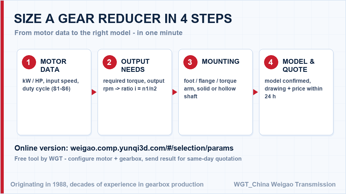
![industrial helical gearbox selection chart]()
A quick visual of the selection sequence for a industrial helical unit.
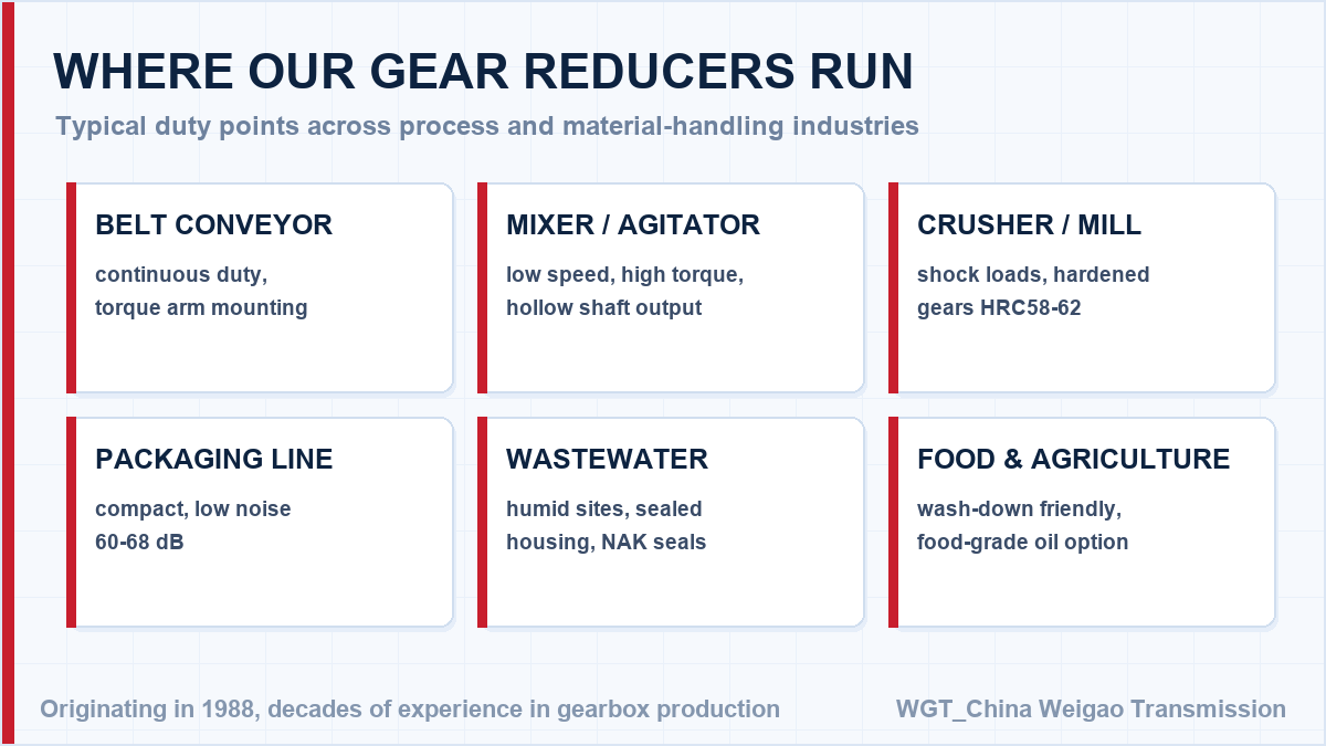
![M3 series gear reducer installation examples]()
Application coverage of the the M3 series.
Custom Shafts and Ratios for OEM Builds
Non-standard interface? Prefer to check the figures yourself? The WGT Motor & Gearbox Online Selection System gives you the model, torque margin and ratio before you ask us.
Splined, extended or flanged output shafts and special ratios are quotable for OEM volumes. Tooling cost is amortised across the order, and the drawing approval cycle starts the day you ask. Looking for a speed reducer for cement plant? Tell us the duty point and we will confirm the model in writing.