Every parallel-shaft family has a stretch in the middle where the catalogue stops being about extremes and starts being about the work most plants actually do. The MC2PLHF04 parallel shaft gear unit belongs to that stretch. The arrangement is the line's own - two helical stages in one horizontal plane, a footed cast case, and a hollow output bore that slides over the driven shaft - but at the fourth frame the torque band widens enough to carry the everyday machinery of a works: the longer screws, the heavier feeders, the second elevators that were never in the original drawing.
What the 04 buys over the frames below it is not drama but reach. Ratios a two-stage train holds comfortably, torques that no longer force a move to the three-stage builds, and a bore sized for the shaft diameters medium-duty machines actually use. On many layouts it is the first frame where the hollow-bore idea stops being a convenience and becomes the default way the machine is put together.
Between the Third and Fourth Frames
The step up shows itself in the parts the torque passes through. Bearing centres widen, the case section thickens across the split line, and the sump deepens enough that the oil mass buffers a long afternoon of load swings instead of following them. The extra metal is quiet benefit: a duty that keeps the third frame working hard leaves the fourth running with audible and thermal room in hand.
What does not change is everything a crew has already learned. The unit still mounts over the shaft, the end plate still closes the assembly against the shoulder, the feet still come down onto shims, and the torque arm still takes the reaction. Training, tooling and spares carry over from the smaller frames, which is one reason plants like to standardise a line across its hollow-bore band rather than mix families frame by frame.
The Type String and the Questions It Settles
Read left to right, the characters on the plate answer most of what a stores clerk or a fitting crew will ask before the crate is even opened.
| MC | Industrial multi-stage gear unit family |
| C2 | Compact two-stage parallel-shaft series |
| P | Parallel stages - input and output shafts in one horizontal plane |
| L | Horizontal build with feet flat on the plinth |
| H | Hollow output bore that mounts over the driven shaft |
| F | Foot mounting with holding-down hardware |
| 04 | Fourth frame - the mid-band of the hollow-bore line |
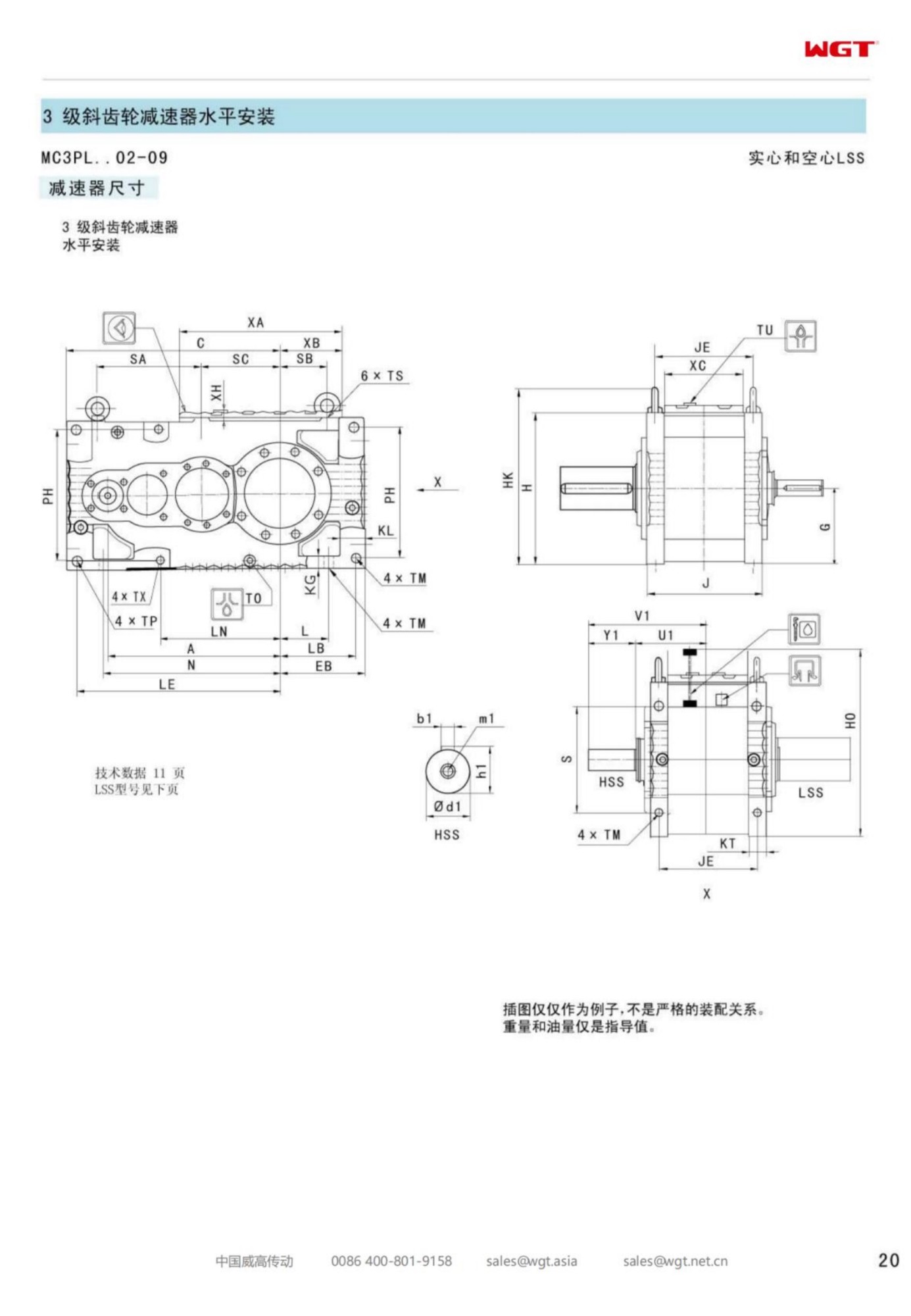
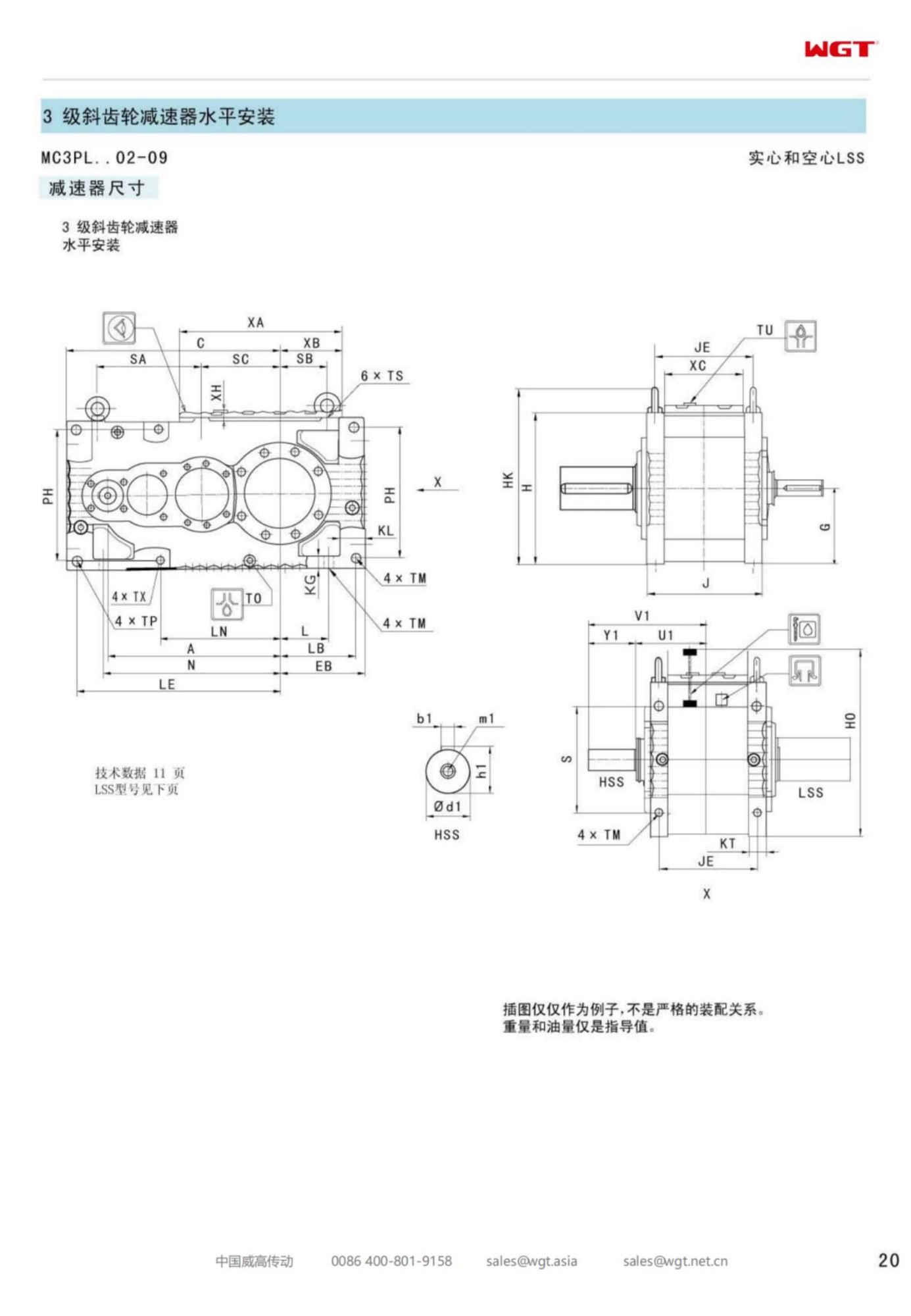
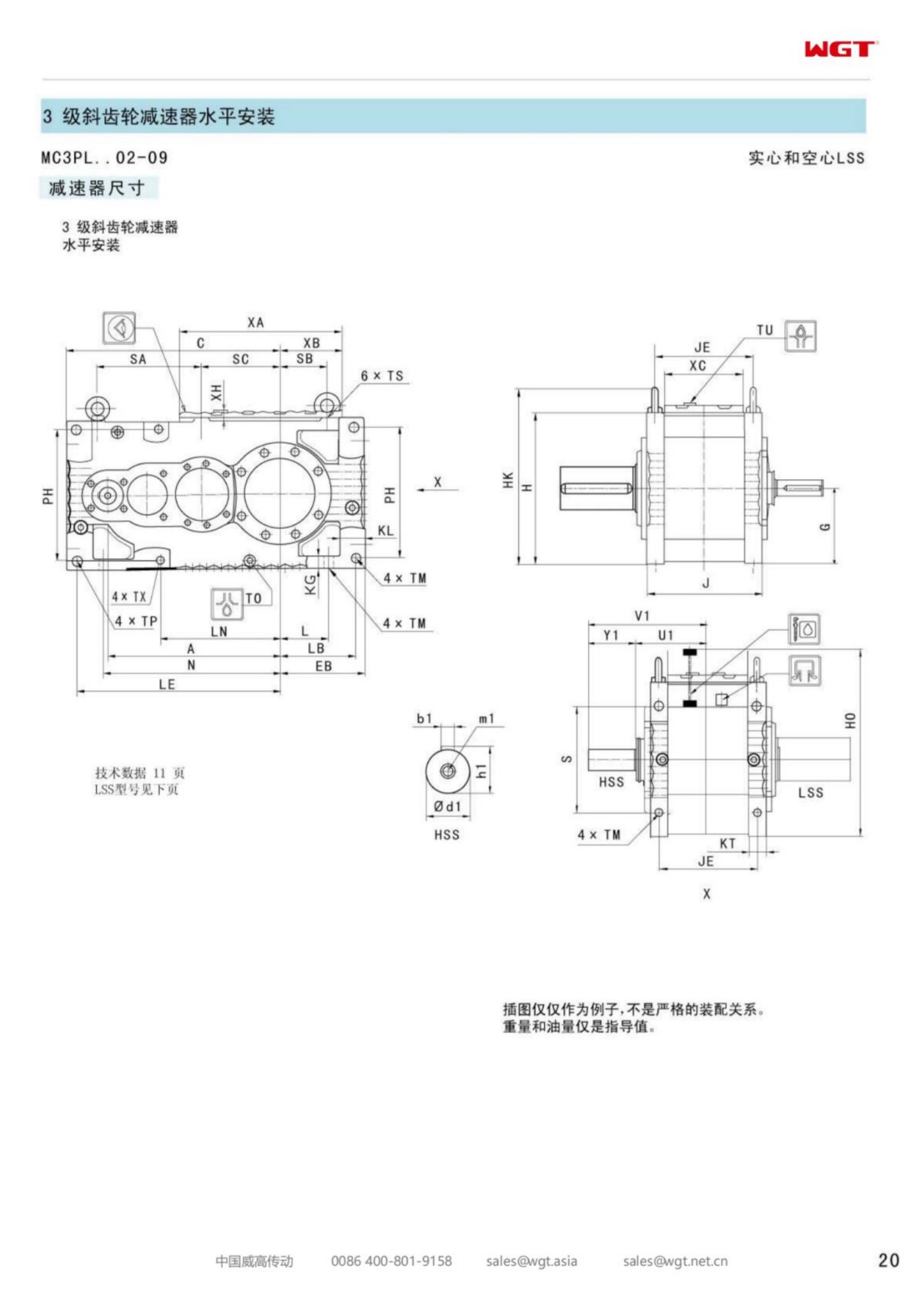
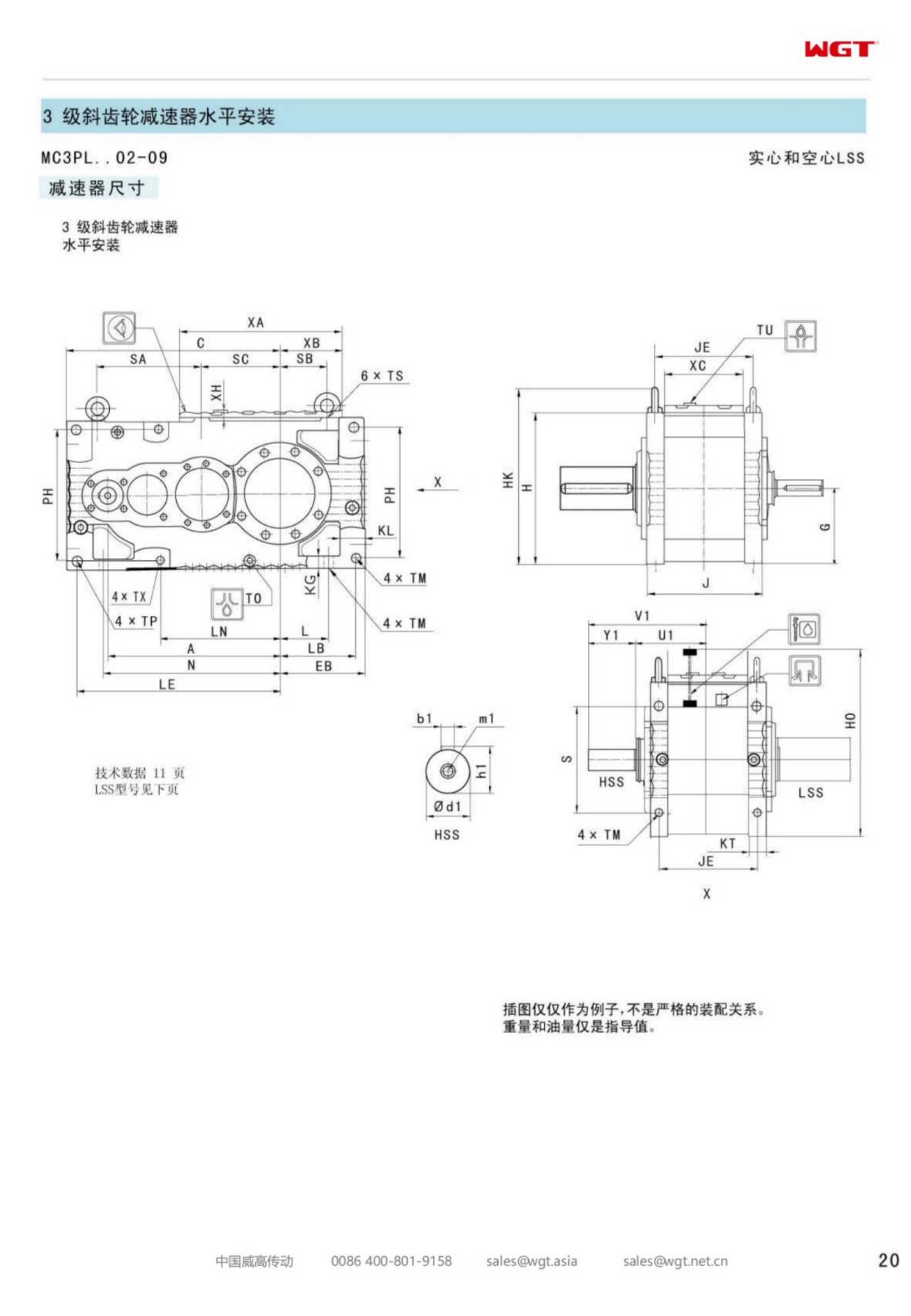
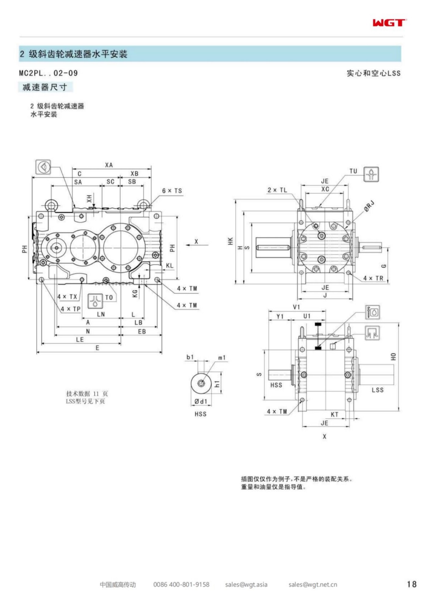
Two characters decide the site work. The H turns the driven shaft into a machine-builder item, delivered to a drawing that travels with the gearbox, so the shaft machining belongs on the project schedule from day one. And the L keeps the drive low and long rather than tall, which is why these units end up beside silo discharge points and inside conveyor gantries where headroom is the constraint nobody wrote down.
Backstops and the Runback Problem
Any inclined machine with a lifted load has a second personality the moment power is removed: it wants to run backwards. Elevators, inclined belts and loaded drag chains all store enough potential energy in the raised material to spin the train in reverse, and the results range from a spillage to a wrecked drive. The answer is a backstop - either built into the gear unit or carried on the motor extension - and it is an order-time decision, not a site-time one.
Declare the runback condition when the unit is specified. A built-in backstop changes the internals, and fitting one afterwards means opening the unit that was supposed to need nothing but oil. On a hollow-bore frame the arithmetic is straightforward: the backstop is rated against the stalled back-running torque of the loaded machine, and that figure comes from the same duty description that sizes the frame. One honest paragraph in the enquiry covers both.
Duties the Fourth Frame Was Sized For
Mid-band machinery this frame was quietly sized for:
- Paddle feeder drives under lime silo discharge hoppers
- Ash drag chain conveyors returning from boiler house basements
- Head shafts of second-stage bucket elevators at aggregate depots
- Pug mill and soil stabilisation mixer drives at a materials yard
- Slat and apron conveyor drives feeding a packing hall
- Scrap and bale conveyor drives at a recycling transfer station
The shared profile is a shaft that already exists, a duty in the middle of the speed band, and a position where the low silhouette of a parallel build earns its place. The hollow bore keeps installation a bolting job rather than an alignment project, and the mid-band frame keeps the drive relaxed on the hours that matter.
Setting Out the Plinth Early
The civil work is the one part of the project with the longest lead time and the least forgiveness, so it deserves to start before the gear unit ships. Bolt pockets are cast to the foundation drawing, the pad is finished to the flatness figure the drawing calls for, and grout quality is checked the same way concrete anywhere is checked. A hollow-bore unit sits low, which means the plinth height is usually set by the driven machine's shaft centre line - measure that on the machine, not on an old layout drawing.
When the unit arrives, the fitting itself is short precisely because the preparation was long. The feet land on shims, the level is taken cold and true, the holding-down bolts are pulled evenly to the specified torque, and the assembly is re-checked after the first thermal cycle. Nothing on that list is difficult; everything on it is cheaper to do well the first time.
Torque Arm Geometry on a Heavier Frame
As frames grow, the torque arm stops being a fitting detail and becomes part of the structure. Its job is to convert the drive's rotation reaction into a pull and a push the building can carry, and the geometry decides how much of each. A longer arm acting on a sound anchor point asks less force of every bolt in the chain; a short, steep arm concentrates load and finds the weak fastener eventually.
Fit the arm at the angle the drawing shows, pin or bolt both ends without preload, and leave the bushing room to flex if the arm has one. The anchor point belongs on primary structure - a frame member, a plinth bracket, something with real stiffness - and never on cladding rails or guard supports. An arm tied to something that moves will teach the whole plant about vibration one seal at a time.
Warm-Up, Cool-Down and the Working Temperature
A mid-frame sump reaches its steady running temperature within the first hour or two of a shift, and from then on the oil temperature is the drive's honest diary. Read it at the same point, on the same round, and the number becomes a trend worth having. A level that slowly climbs across weeks says the duty has grown or the cooler has blinded; a level that jumps in a day says something happened, and the sample bottle will say what.
Cold mornings deserve their own note. Thick oil on a January start is normal for a few minutes, and the drive warms as it runs - but a unit that moans for half an hour every winter morning is asking for the correct viscosity grade for the climate, not for sympathy. The grade table in the instruction book covers the ambient band; matching it costs one oil decision and returns years of easy starts.
Sound as a Diagnostic
Experienced ears sort a gear unit's health faster than most instruments. A correct installation settles into one even note that rises gently with load. A knock at shaft frequency points at the key or the bore fit; a whine that tracks speed points at mesh or alignment; a gravel note that never quite settles points at the bearings and deserves an earlier look than the calendar planned.
The habit that turns listening into maintenance is the baseline. Twenty minutes at commissioning, with sound, temperature and vibration notes written down, gives every later inspection something to compare against. The comparison is what converts a vague feeling that the drive sounds different into a planned bench visit instead of an unplanned stop.
When the Shaft Was Not Machined for This Bore
Plenty of hollow-bore purchases are retrofits onto machines that were built around couplings, and the driven shaft rarely matches the bore drawing on the first look. The honest paths are two. Either the shaft is machined to the unit's bore specification - diameter and tolerance, surface finish, keyway, shoulder - which a competent shop does quickly, or the enquiry is reopened and the bore is matched to the shaft as it exists. What does not work is persuading the fit with heat, glue or hope.
Involve the supplier with the shaft drawing before the order, not after the crate arrives. The outline drawing that comes back with the quotation is the machine shop's work order, and a week spent on that exchange is recovered the day the unit slides onto a shaft that fits the first time.
Details That Keep the Quotation Moving
A fourth-frame enquiry quotes in one pass when it carries the duty and the fitting together. Driven machine and load pattern, with jam and stall conditions named. Motor power, speed and starting method. Output speed and the tolerance the process accepts. Hours per day across a real week. Ambient conditions stated plainly. Then the fitting half: shaft diameter and keyway, usable length, shoulder dimension, torque arm side and anchor point, rotation direction, and whether the duty can run back under load - the backstop question - in writing.
With those lines filled, the return is a firm quotation, an outline drawing for the shaft and a delivery date the project can build around. Without them, the file waits on dimensions that were knowable on day one, and the site waits on the file.
Selection Example: Paddle feeder drive under a lime silo discharge hopper
Take a 15 kW motor at 1460 rpm turning the paddle feeder at 43 rpm. The ratio follows directly: 1460 / 43 = 34, so a ratio near i=34 is drawn from the two-stage band, and the frame is checked against the stall that follows a feeder bridged over by compacted lime after a humid week. In this case the fourth frame turns that duty with room in hand at the middle of the band, and the hollow bore drops over the feeder shaft from a footed case that sits low beside the silo. That is the whole calculation. If your duty involves heavy starting, frequent reversing or many stops per hour, tell us and we raise the service factor.
Which Frame Size Do You Need?
| Model | Centre distance | Output | Typical duty |
|---|
| M3PSF50 | size 50 | solid shaft, foot | conveyors, feeders |
| M3PSF60 | size 60 | solid shaft, foot | crushers, mixers |
| M3PSF70 | size 70 | solid shaft, foot | ball mills, shredders |
| M3PSF80 | size 80 | solid shaft, foot | kilns, heavy conveyors |
| M3PSF90 | size 90 | solid shaft, foot | mill and kiln drives |
| M3RSF50 | size 50 | solid shaft, foot, right-angle | inclined conveyors, elevators |
| M3RSF60 | size 60 | solid shaft, foot, right-angle | screw classifiers, feeders |
| M3RHF70 | size 70 | hollow shaft, foot, right-angle | agitators, drum drives |
| M3PHT80 | size 80 | hollow shaft, torque arm, parallel | shaft-mounted conveyors |
| M3RHT90 | size 90 | hollow shaft, torque arm, right-angle | heavy shaft-mounted drives |
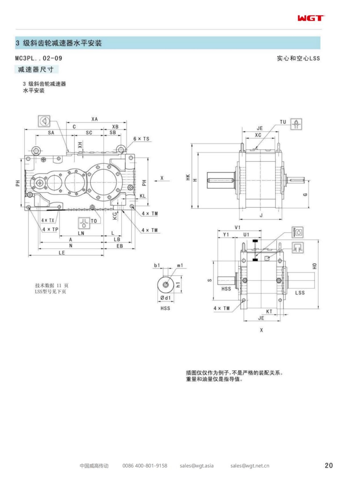
Foot-mounted frames are listed below; torque-arm (T), hollow-shaft (H) and vertical (V) variants are available across the size range. Ask for the outline drawing to check the interface before ordering.
Answers to Common Questions
Can you manufacture a custom ratio or a special shaft?
Beyond the catalogue ratios we can quote special ratios and custom output shafts - splined, extended, special keyways or drilled - for OEM volumes. Tooling is amortised across the order, so unit cost falls as quantity rises.
Will the unit match my existing gearbox interface?
The series is manufactured to the standard centre distances, shaft dimensions and flange patterns of its frame family, so couplings, guards and foundations do not have to be redesigned. Send the nameplate details and we confirm the equivalent frame in writing.
What is the maximum overhung load on the output shaft?
The permissible overhung load depends on frame size, output speed and the distance from the shaft shoulder - all listed in the catalogue. If you drive a chain sprocket or V-belt pulley direct on the output shaft, send us the load and pitch diameter and we will confirm the limit.
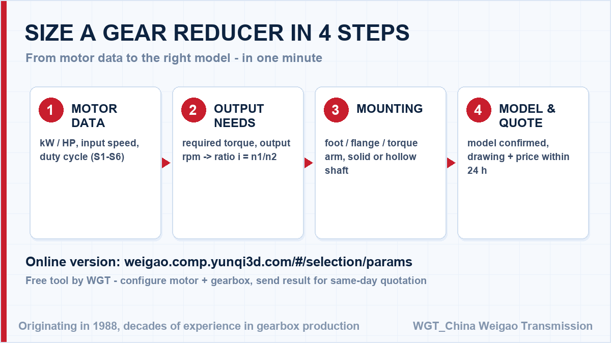
![gearbox sizing steps for engineers]()
Four steps from your application data to a firm model number.
Case Notes from the Field
Overland conveyor system
A mining company drives a two-kilometre overland conveyor with heavy-duty helical gear units at the head station. Continuous 24-hour duty, frequent starts under full load and minimal maintenance windows were all part of the specification.
Cement plant bucket elevator
A cement works renewed the gear units on its bucket elevators during a kiln shutdown. The new units bolted onto the old foundations without modification, and the elevator was back in service within the planned window.
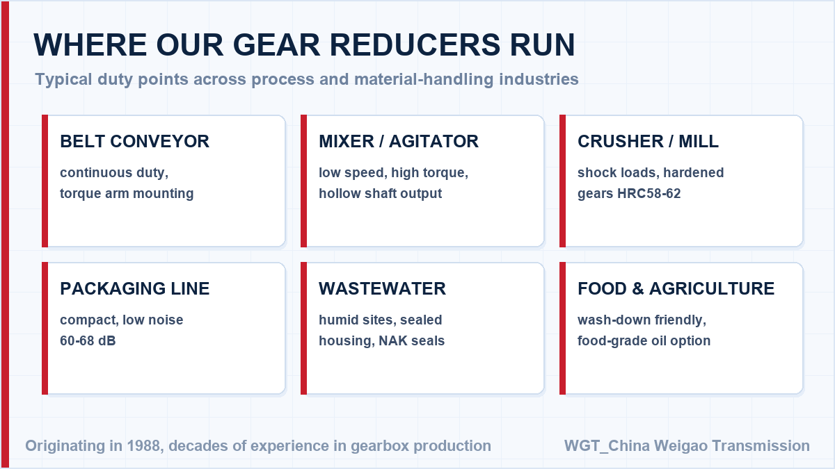
![industrial gear unit application overview]()
A cross-section of the installations we supply every month.
Engineering Support Before You Buy
Unsure about the frame size? Try the WGT Motor & Gearbox Online Selection System, then send the result sheet - we return a complete datasheet, drawing and price the same day.
Our selection engineers check every enquiry against the rating tables, including shock class and daily running hours. You get the calculation, not just a part number - at no charge and with no obligation. Looking for a gearbox for wastewater treatment? Tell us the duty point and we will confirm the model in writing.