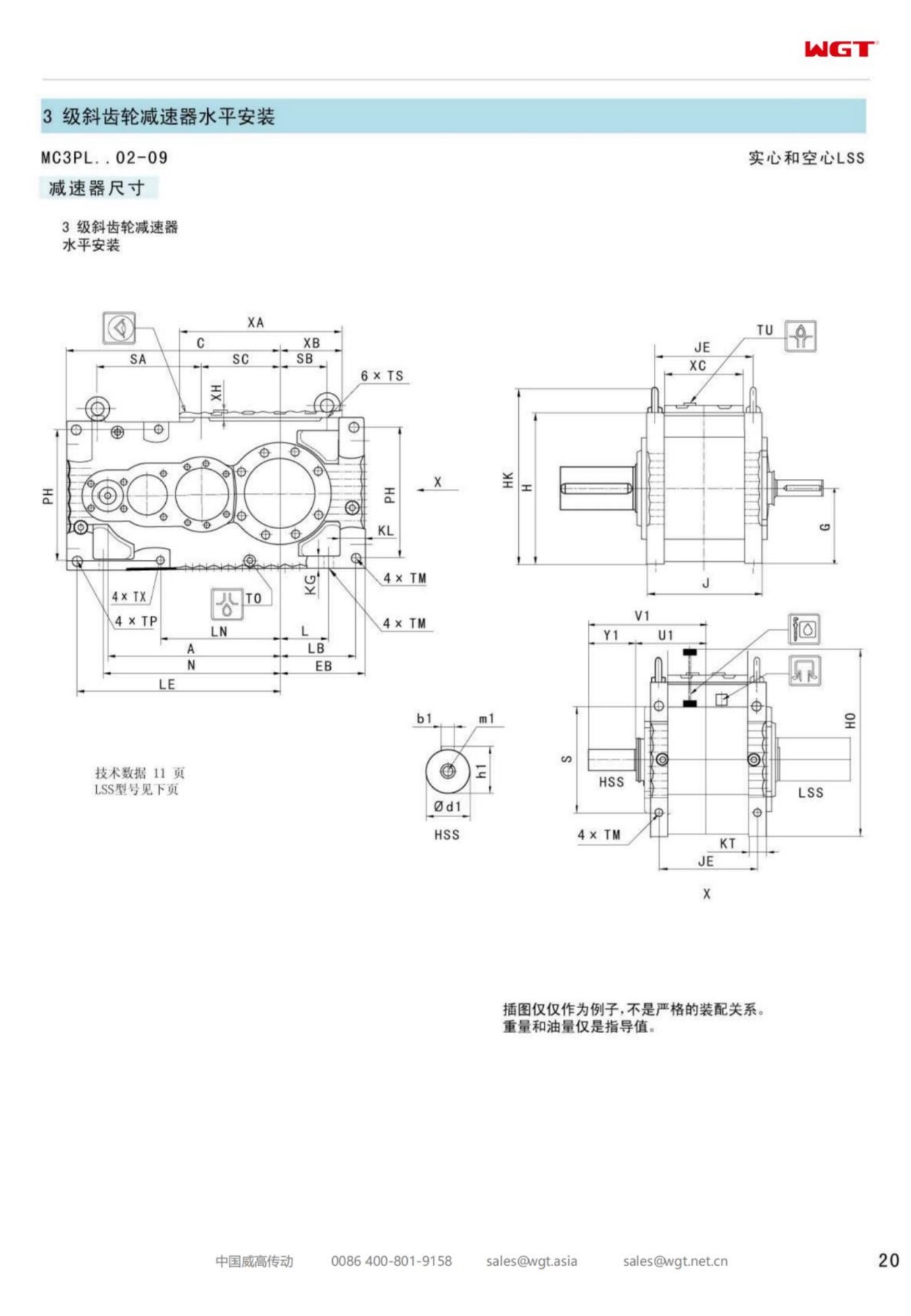
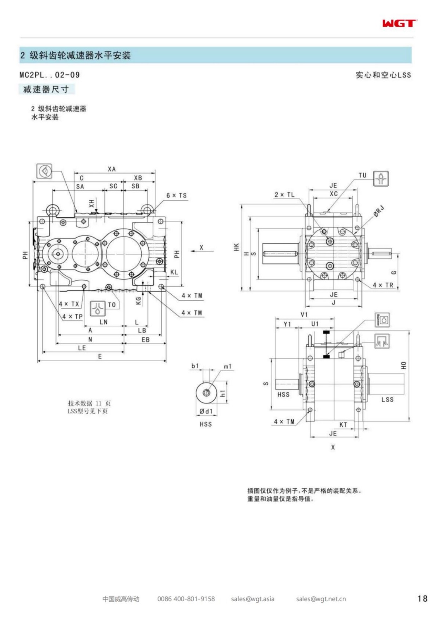
Most gear units arrive at a plant with a foundation drawing attached, and the project pays for that foundation three times: once in concrete, once in the millwright's hours, and once again in the alignment report nobody reads until something starts to hum. The MC2PLHT02 shaft-mounted gearbox removes that whole sequence from the schedule. It slides over the driven shaft, is keyed to it, and is held against rotation by a torque arm bolted to the machine frame. No plinth, no grout line, no coupling to align.
At the small end of the industrial band this is not a shortcut taken to save money. It is a layout decision, and plants make it when the driven shaft is already a structural element in its own right - a conveyor head shaft, an elevator head shaft, the tail of a screw conveyor - and when the floor beside the machine is better used for access than for a gear case and its bedplate.
A Gearbox That Hangs on the Machine's Own Shaft
The reasoning is old and stubbornly practical. If the machine already carries a shaft strong enough to take the process load, that shaft is strong enough to carry the drive that turns it. Mounting the unit on the shaft removes the parallel error a flexible coupling can never fully hide, and it removes a foundation that would otherwise have to be designed, poured, cured and inspected before the drive could be commissioned at all.
What looks like a simplification has terms attached, and they are worth understanding before the order goes in. The gear case now shares the driven shaft's deflection. Its bearings become part of the machine's load path. And the reaction torque has to be handed to structure that may have been built years before anyone thought about a gearbox. None of these are problems. They are simply the terms of the arrangement, and they are cheapest to settle while the drawing is still open.
Decoding MC2PLHT02
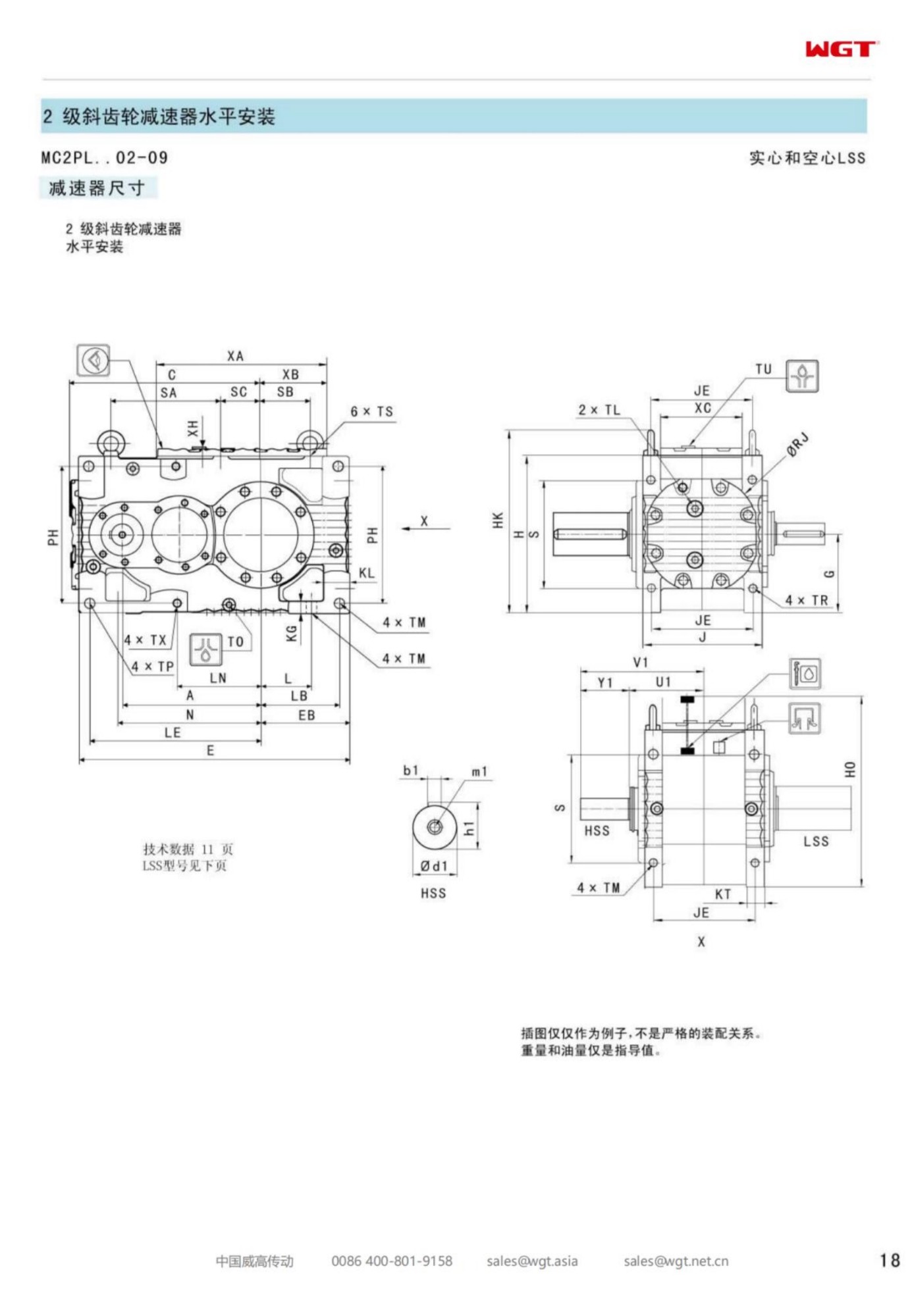
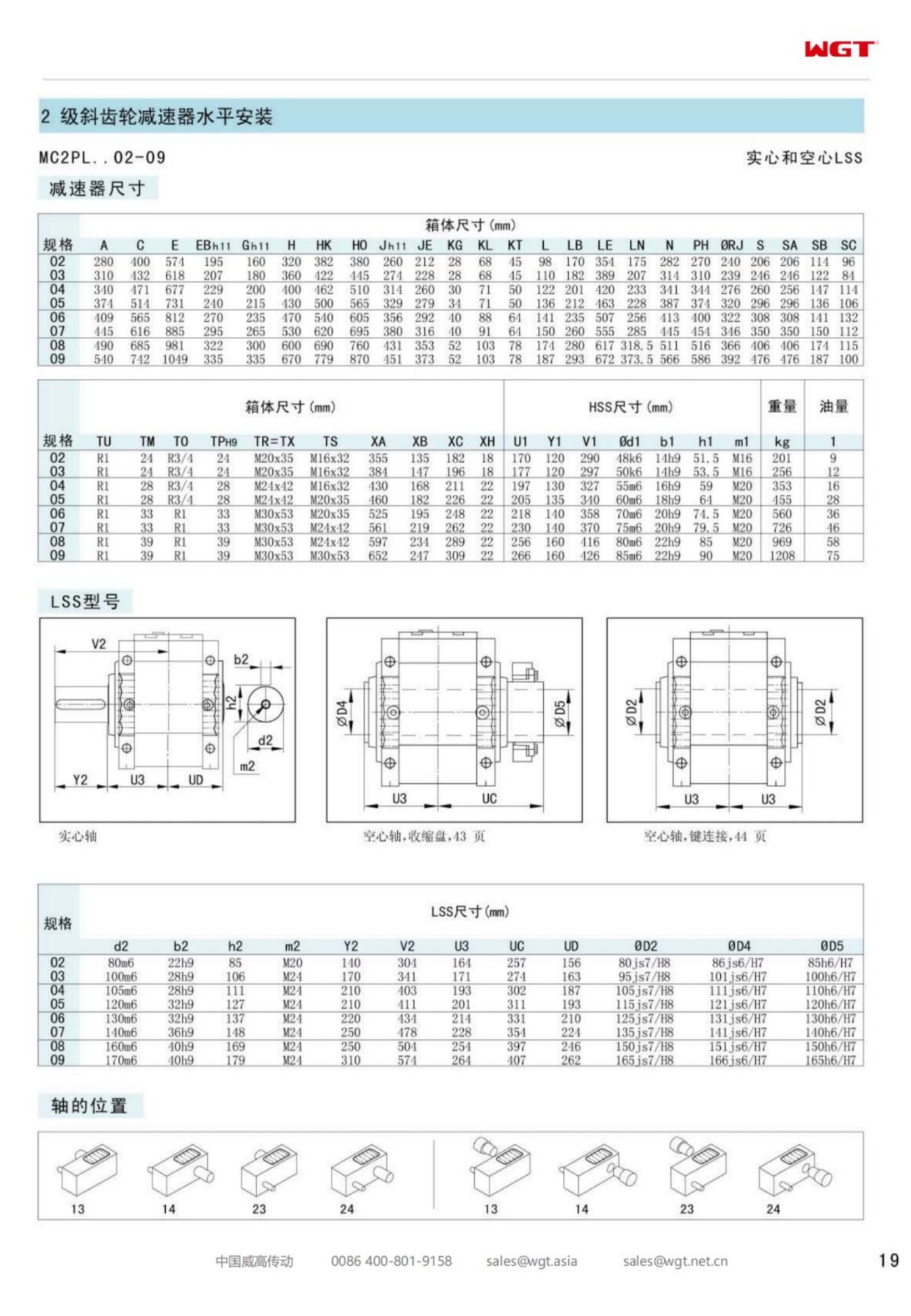
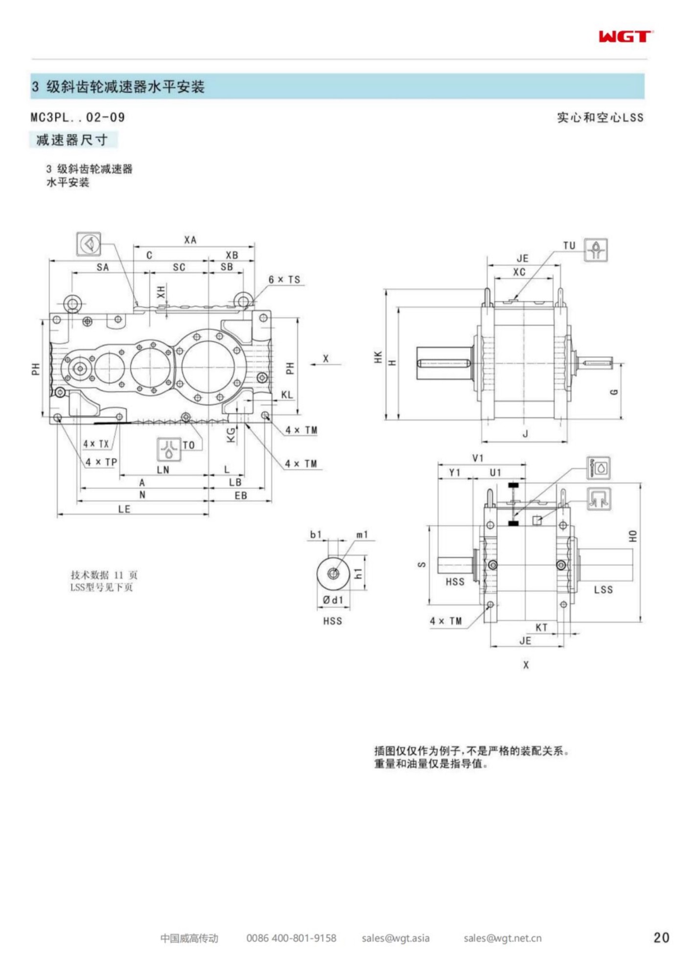
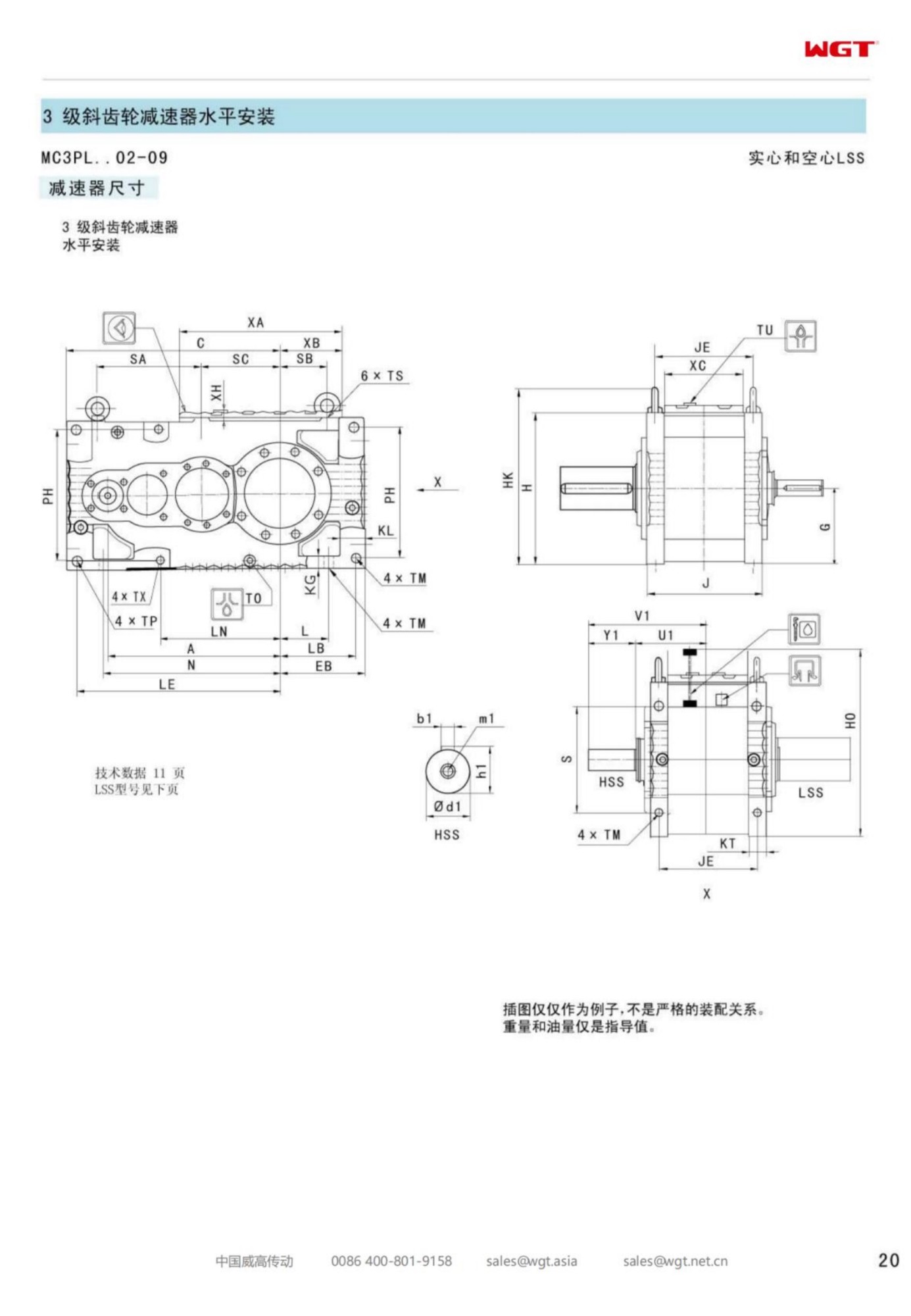
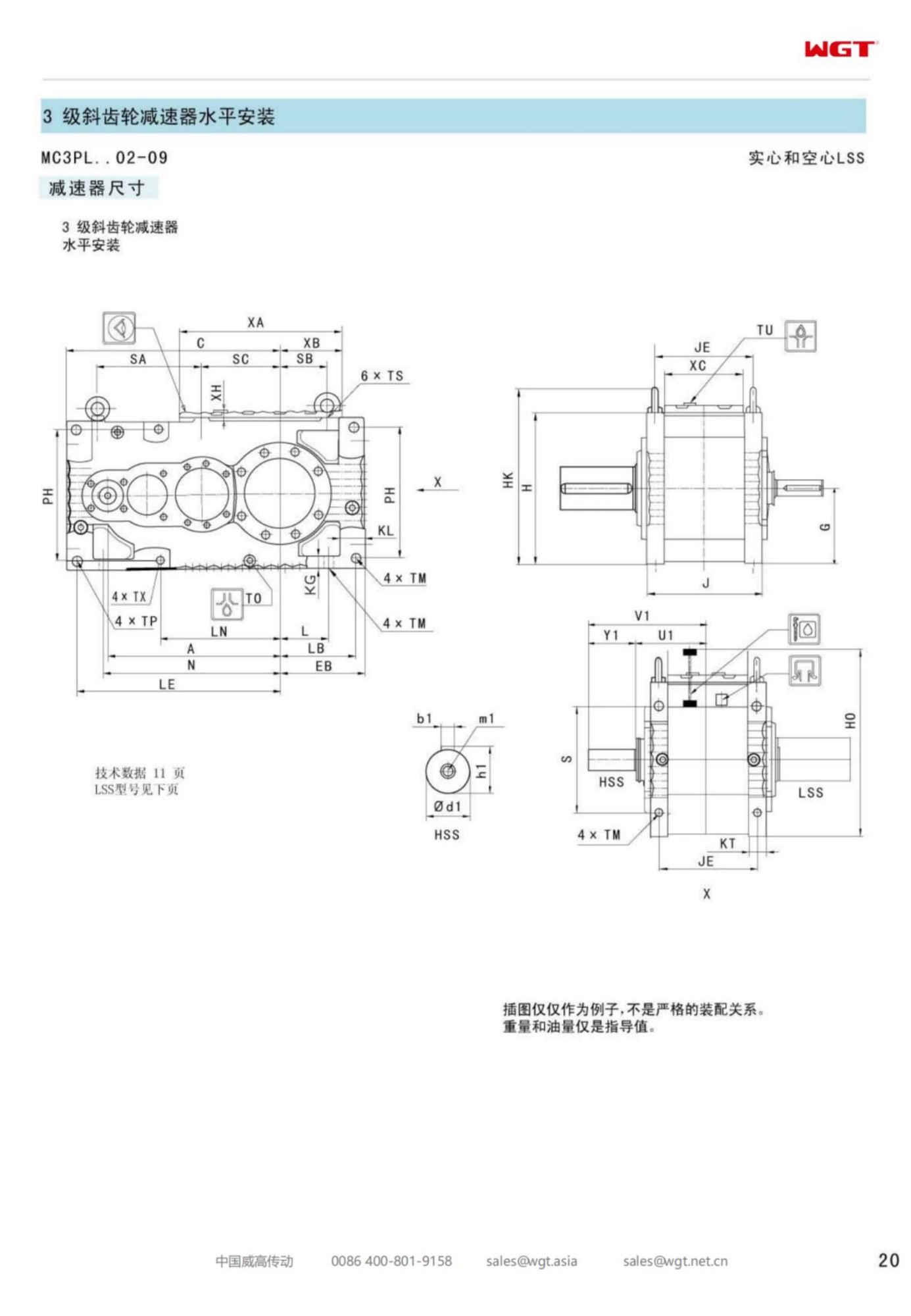
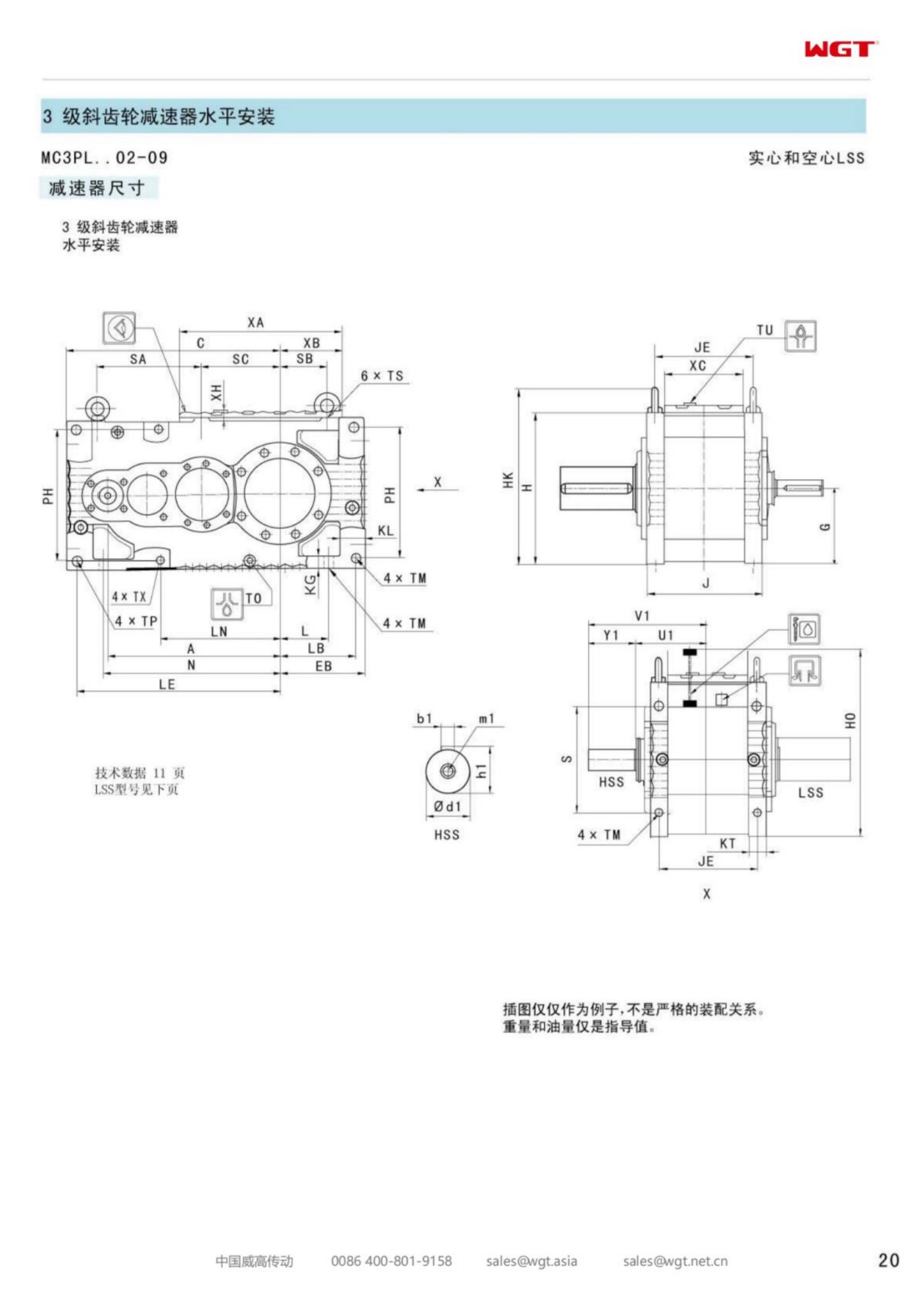
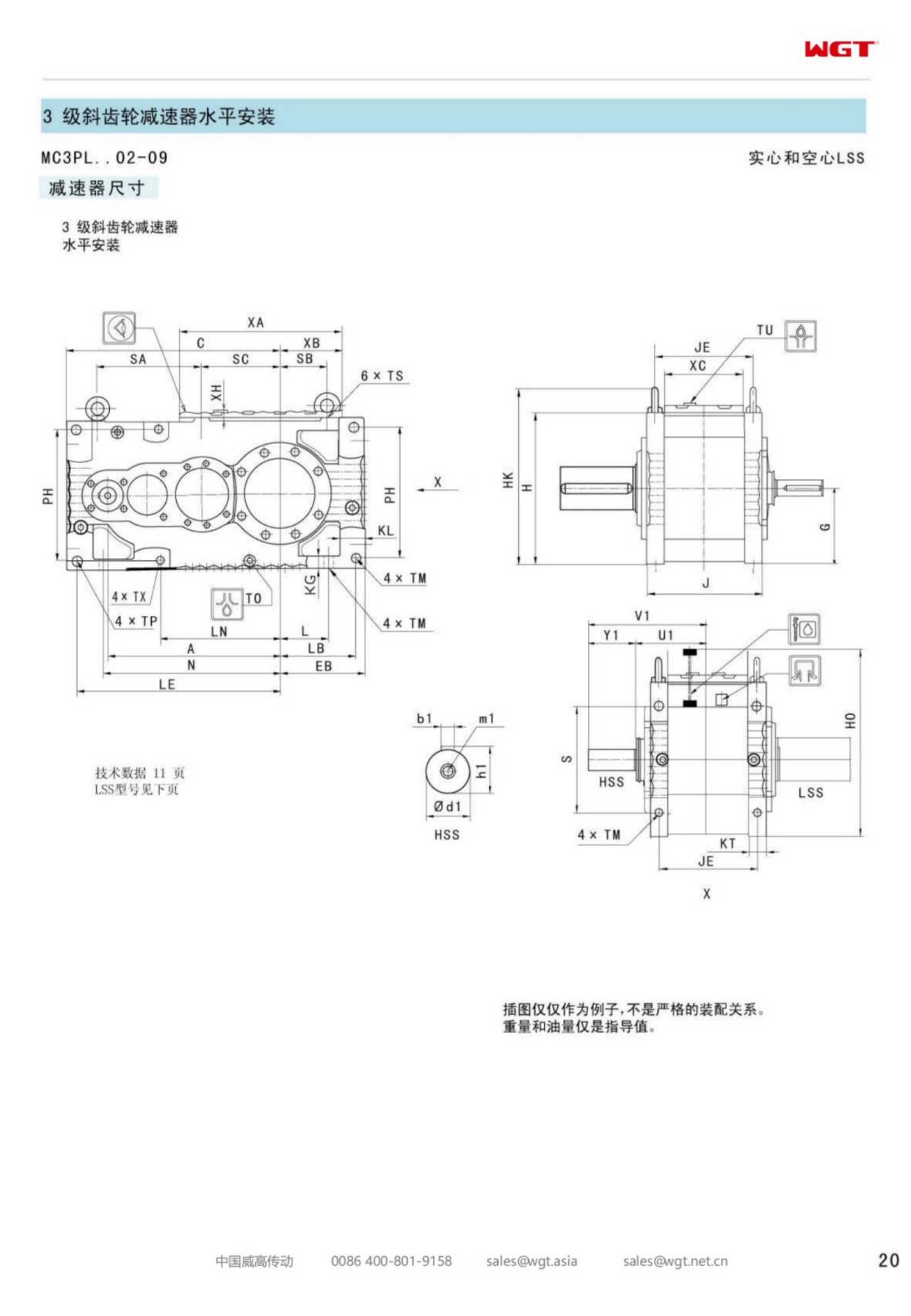
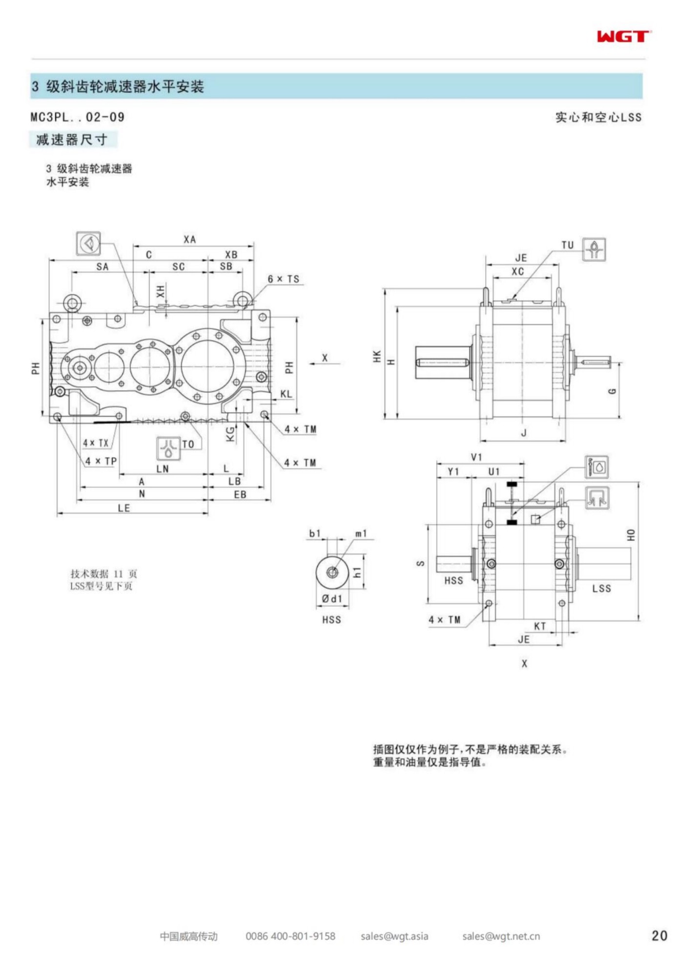
Each character in the type string records a decision already taken by somebody. Reading it once against the outline drawing prevents most of the correspondence that follows a wrong delivery.
| MC | Industrial gear unit family built for continuous plant service |
| 2 | Two reductions in train: two helical stages in one plane |
| P | Parallel-shaft layout, input and output shafts parallel |
| L | Level build, both shafts horizontal in a common case |
| H | Hollow output bore that mounts over the driven shaft |
| T | Torque arm mounting, no feet and no foundation |
| 02 | Second frame of the band, at the light end of the range |
The string stays silent about the choices that cost weeks when they are missed: which side the motor mounts, where the breather must face to survive washdown, and which direction of rotation the duty actually runs. Each is one line on an order confirmation, and each is expensive once the case is cast.
Why Plants Choose Shaft Mounting at This Size
Three arguments come up again and again, and all three are about the space around the machine rather than about the gearbox itself. First, the drive occupies no floor: it hangs on the shaft, beside or above the equipment, and the walkway underneath stays a walkway. Second, there is no coupling to wear, guard, align or inspect - one fewer assembly in the maintenance plan and one fewer source of vibration. Third, installation happens in an afternoon with a chain block and one fitter, not in a week with a contractor and a concrete lorry.
There is a fourth argument that rarely gets written down and decides many purchases: a shaft-mounted drive is difficult to install badly. A footed unit on a soft plinth can be bolted down with a twist that takes a season to show itself, whereas a unit that locates on a machined shaft has far fewer ways to go wrong once the bore fit has been checked. That is worth real money on a site where the crew changes with the contract.
The Torque Arm and the Structure It Pushes Against
The arm is the least glamorous component on the machine and the one that fails first when the layout is rushed. Its job is to take the reaction torque and pass it into the machine frame without imposing a bending load on the gear case. That means the anchor point must be stiff in the direction of the reaction and free in the others, which is why the connection is normally a bushing or a resilient element rather than a rigid bracket welded wherever steel happened to be.
Two habits keep the arrangement sound. Anchor to structure that was designed to take a torque, not to guarding or to a handrail post that a forklift can find. And leave the arm's freedom of movement as drawn - if the arm is clamped so tightly that it cannot accommodate the small movement the shaft makes under load, the reaction goes into the case and the bearings pay for it. Where the machine frame is light, a short bracket back to a stiffener is cheaper than a heavier gearbox.
Fitting the Bore to a Real Shaft
The bore is where this build either earns its reputation or starts a long argument. Check the shaft diameter against the drawing, check the key for fit and for length, and check the plain length available against the bore so the unit does not bottom out with the retaining hardware still loose. Clean both surfaces, apply the specified anti-fretting preparation, and slide the unit on with its weight supported - never hanging on the bore edges.
Then measure, and write the numbers down. A bore that went on with a hammer is a bore that will fret. A shaft machined to the low side of tolerance, meeting a bore at the high side, produces a fit that holds torque on the key but rocks under reversing load - and reversing load is what most conveyors and feeders actually deliver. Where the shaft diameter is marginal, a machined sleeve or a light build-up is a better answer than a bigger hammer, and both are decisions to take before the unit leaves the ground.
Service Factor With No Coupling to Absorb the Shock
A coupling is a filter. It absorbs a little misalignment, a little torsional shock and a little of the abuse a driven machine hands back at start-up. Remove it and every one of those arrives at the gear teeth instead. That is not an argument against shaft mounting - it is an argument for reading the duty class honestly at the selection stage.
Three figures carry most of the risk. Starts per hour, because every start loads the mesh from zero. Breakaway torque at the worst condition, because a conveyor started full is not the same machine as a conveyor started empty. And the material's behaviour at rest, because lime, cement, sugar and wet coal all set, and each of them asks for a multiple of running torque to get moving again. An enquiry that states those three gets a frame whose factor means something; one that states a motor rating gets a frame chosen against a table that cannot see the plant.
The First Frame in a Line of Continuous Duty
The first frame of the torque-arm band is bought by plants that want the drive on the shaft, not on a plinth:
- Screw conveyor drive at a grain intake pit
- Bucket elevator head shaft at a small feed mill
- Slat conveyor drive on a bottling line infeed
- Rotary valve drive under a bag filter hopper
- Through-shaft agitator on a small slurry holding tank
- Belt conveyor head pulley at a quarry screening plant
What those duties share is hours rather than torque. None of them is dramatic, and most run unwatched for eight thousand hours a year - more running time than any headline machine in the works. A frame chosen with an honest factor at this end of the band quietly outlasts three of its neighbours; a frame chosen on price alone becomes the recurring line in the maintenance log.
Oil Level in a Housing That Can Sit at an Angle
A shaft-mounted case can be installed in more than one orientation, and the level plug is correct only for the orientation it was set for. That sounds trivial until a unit is mounted with the plug on the wrong face and filled to the wrong line, which produces either a starved bearing or a churning sump that runs hot from its first day. State the mounting position on the order, and check the drawing that comes back against the angle the machine actually presents.
Once installed, the level check belongs to a fixed routine rather than to memory. A weekly look at the glass or the level plug, a note of any top-up volume, and an oil sample at the first change and yearly after that will find a failing seal long before it finds a bearing. Small sumps are unforgiving: a few grams of water or wear metal is a large fraction of the volume, so the readings move early and the diagnosis is easy - provided somebody is writing them down.
Taking the Unit Off Without Dismantling the Line
The question that separates a good layout from a merely workable one is what happens when the drive has to come off. On a shaft-mounted unit the answer depends on two details settled at order time: whether the driven shaft has enough plain length beyond the bore to let the unit be drawn back, and whether the torque arm can be released without stripping half the machine's guarding.
Where the layout is tight, a bore with a withdrawal arrangement and a shaft prepared with a pulling thread turns a day's work into an hour's. Where it is not, the crew invents a method on the day, and invented methods are how bores get scored and shafts get burred. A paragraph on the enquiry - how the unit will be removed, and by whom - is the cheapest access planning available.
What the Enquiry Has to Say
Everything a selection engineer needs is short. Motor power, speed and starting method. Driven machine, its load pattern, starts per hour and breakaway condition. Output speed and the tolerance the process accepts. Hours per day, and the worst hour described in words rather than averages. Ambient, including washdown and steam. Driven shaft diameter, key, and the plain length available for the bore. Mounting position, motor orientation and rotation direction. Paint and documentation requirements.
Sent complete, that list comes back as a firm quotation, an outline drawing that fits the first revision of the layout, and a delivery date that suits the shutdown. Sent as a power figure and a shaft size, it comes back as questions, and each round of questions costs a week. The frame is small. The delay it can cause is not.
The First Month Tells You Everything
A new drive declares its intentions early. In the first four weeks the oil level either holds or drops, the case temperature either plateaus or climbs, and the sound of the mesh either settles into a hum or develops a note at one particular speed. Recording those three things at commissioning and again after a month turns every later reading into a trend instead of an opinion.
The same month is the right time to confirm the installation was what the drawing intended: the arm free to move, the bore dry and clean at its edges, no fretting dust, no oil weeping at the seal. Ten minutes with a torch and a notebook, done while the paint is still fresh, is the difference between a drive that is serviced and a drive that is discovered.
Field Applications
Pet-food extruder feeder
A pet-food plant chose reducers for the feeder screws ahead of its extruders. Steady torque at variable output speed keeps the kibble size consistent, and washdown sealing protects the unit during sanitation shifts.
Ceramic tile press feeder
A ceramic tile producer fitted reducers to press feeders. The dusty environment is handled by sealed housings, and the stable low-speed output stops the tile blanks shifting before pressing.
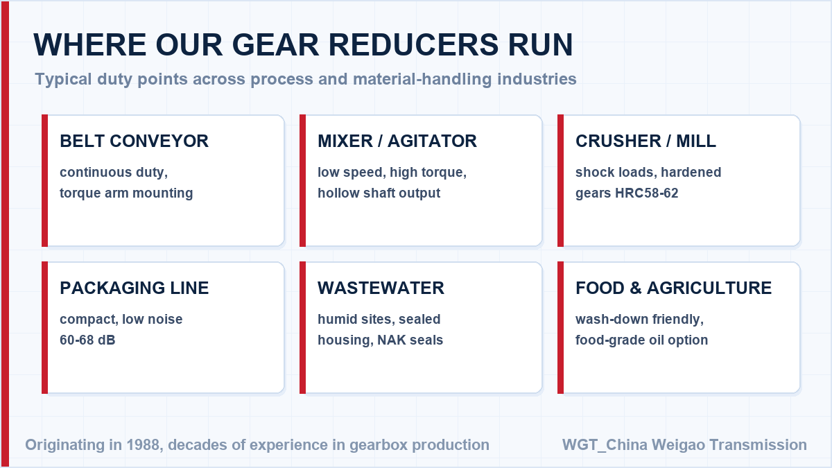
![where gear reducers are used in industry]()
Where these units are installed across industry.
Selection Example: Screw conveyor drive on a grain intake pit
Take an 11 kW motor at 1460 rpm turning the screw at 47 rpm. The ratio follows directly: 1460 / 47 = 31, so a ratio near i=31 is drawn from the two-stage band, and the frame is checked against the breakaway of a trough that has stood full of damp grain over a weekend. In this case the unit hangs on the screw tail shaft with its torque arm tied back to the pit frame, so no bedplate, coupling or grouted plinth has to be built in a pit that floods twice a year. Once the ratio is fixed, check the required output torque against the rating table with the service factor applied - that is what decides the frame, not the ratio alone.
![gearbox selection guide: speed, torque, service factor]()
How a ratio and a frame size are determined, step by step.
Frame Sizes and Typical Duties
| Model | Centre distance | Output | Typical duty |
|---|
| M3PSF50 | size 50 | solid shaft, foot | conveyors, feeders |
| M3PSF60 | size 60 | solid shaft, foot | crushers, mixers |
| M3PSF70 | size 70 | solid shaft, foot | ball mills, shredders |
| M3PSF80 | size 80 | solid shaft, foot | kilns, heavy conveyors |
| M3PSF90 | size 90 | solid shaft, foot | mill and kiln drives |
| M3RSF50 | size 50 | solid shaft, foot, right-angle | inclined conveyors, elevators |
| M3RSF60 | size 60 | solid shaft, foot, right-angle | screw classifiers, feeders |
| M3RHF70 | size 70 | hollow shaft, foot, right-angle | agitators, drum drives |
| M3PHT80 | size 80 | hollow shaft, torque arm, parallel | shaft-mounted conveyors |
| M3RHT90 | size 90 | hollow shaft, torque arm, right-angle | heavy shaft-mounted drives |
The size number is the key dimension that steps up torque capacity through the range: 50 to 90 in horizontal builds, 10 to 90 in vertical builds. Gearing philosophy is shared across the family.
From Duty Point to Delivery in One Working Day
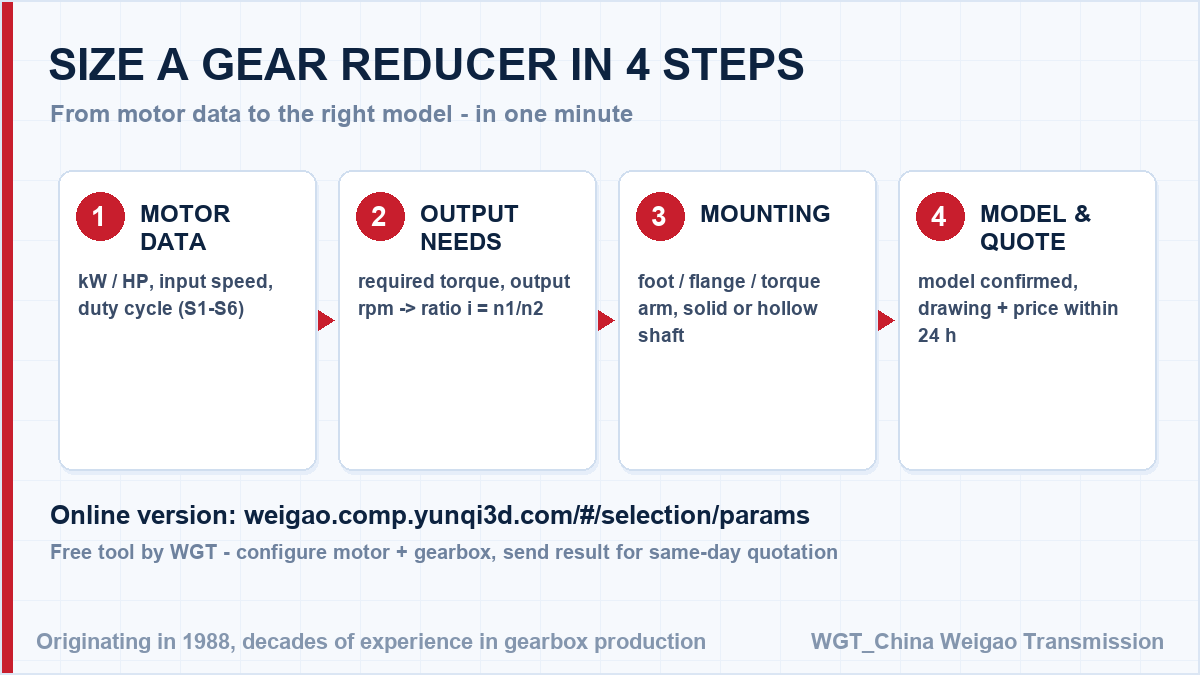
Stop guessing the ratio. Engineers can size the unit themselves in the WGT Motor & Gearbox Online Selection System - input speed, torque and duty, get the model instantly.
Tell us what the machine does and how hard it works; we calculate the ratio, apply the service factor and send back the drawing and quotation within one working day, including sea-freight and air-freight options. Looking for a gearbox for wastewater treatment? Tell us the duty point and we will confirm the model in writing.
Common Questions from Buyers
What is the difference between a keyed hollow shaft and a shrink-disc connection?
A keyed hollow shaft is the economical choice for normal torque and easy maintenance. A shrink-disc connection transmits higher torque with zero backlash and no keyway wear, and is preferred for reversing or high-torque duties.
Can I get a CAD drawing or 3D model for my design review?
Yes. Send us the model and ratio and we provide a 2D dimension drawing and a 3D STEP model for your review, usually the same working day. Drawings follow the layout of the original series so they drop into your existing assembly.
What is the recommended oil change interval?
The housing is lubricated for life under normal duty and normal ambient. In hot, humid or continuous service, change the oil after the first 400 running hours and then every 4000 hours, or once a year, whichever comes first.