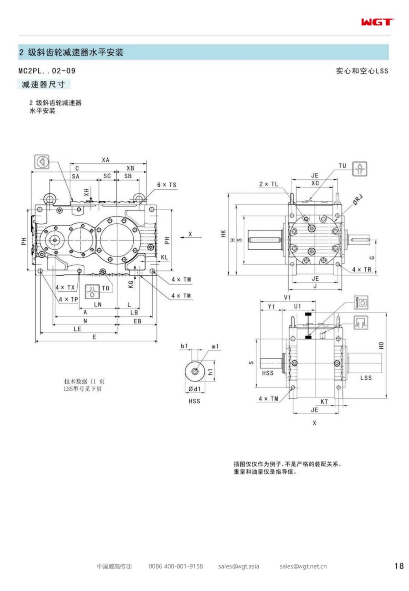
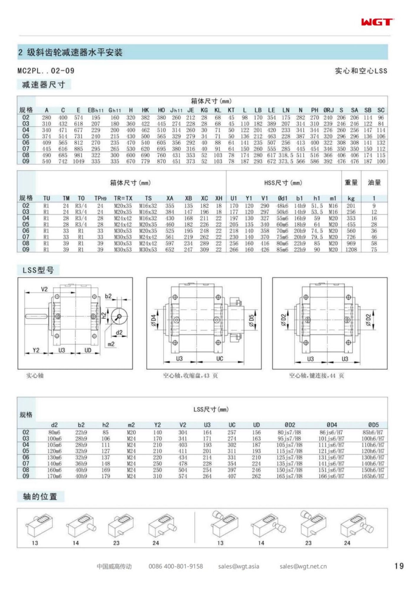
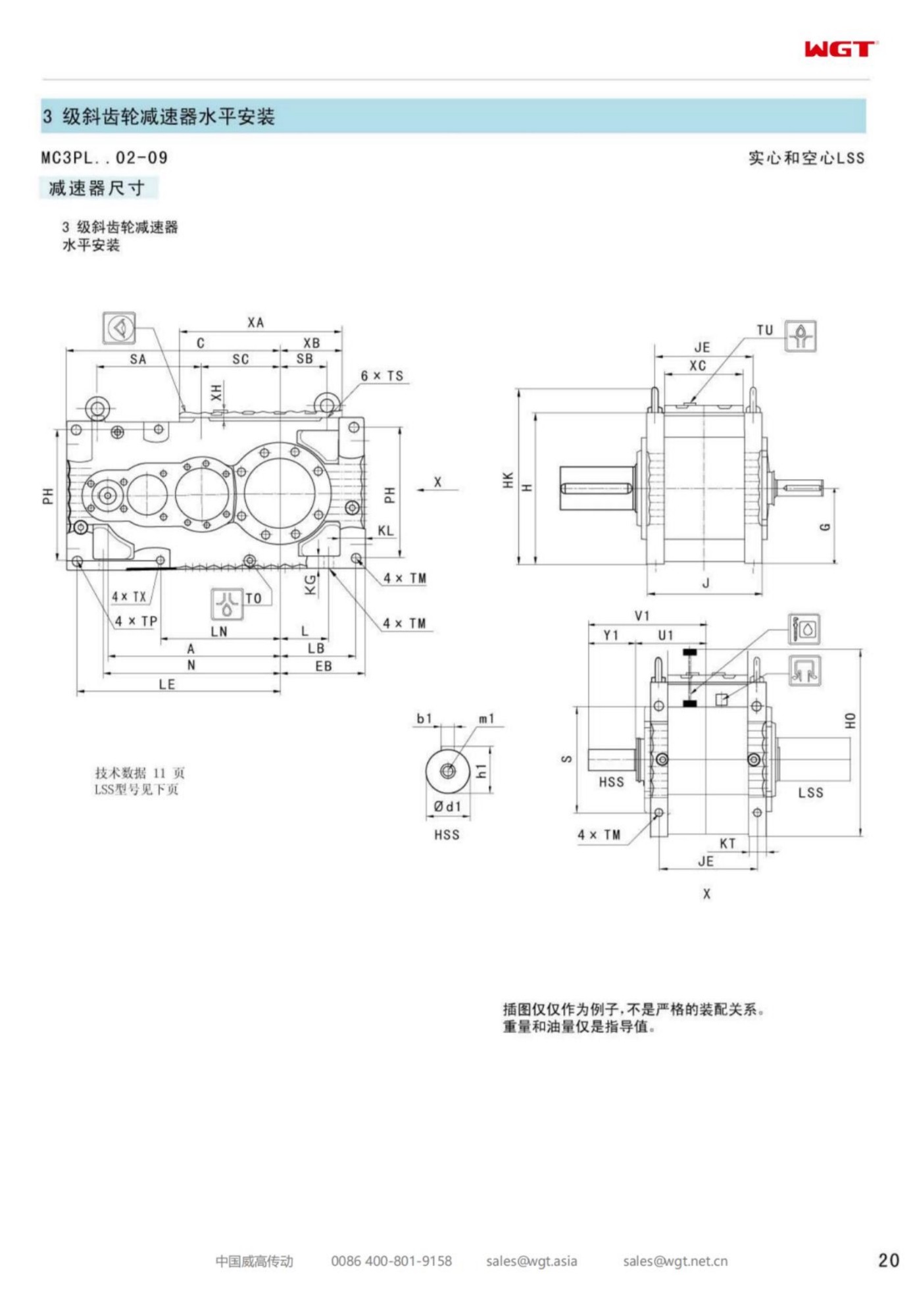
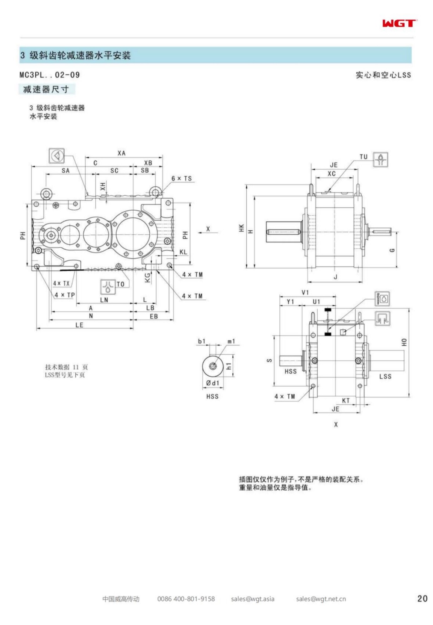
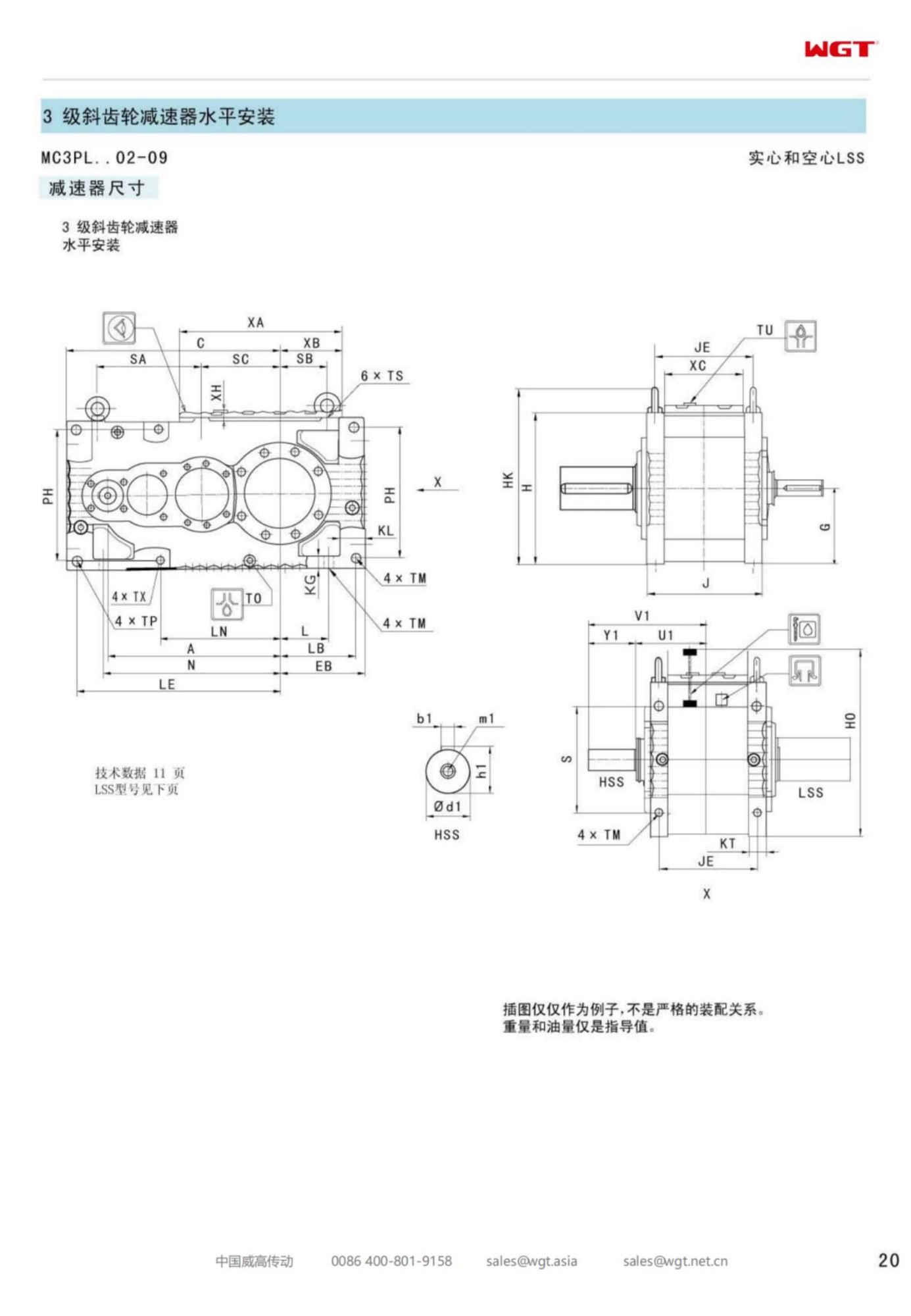
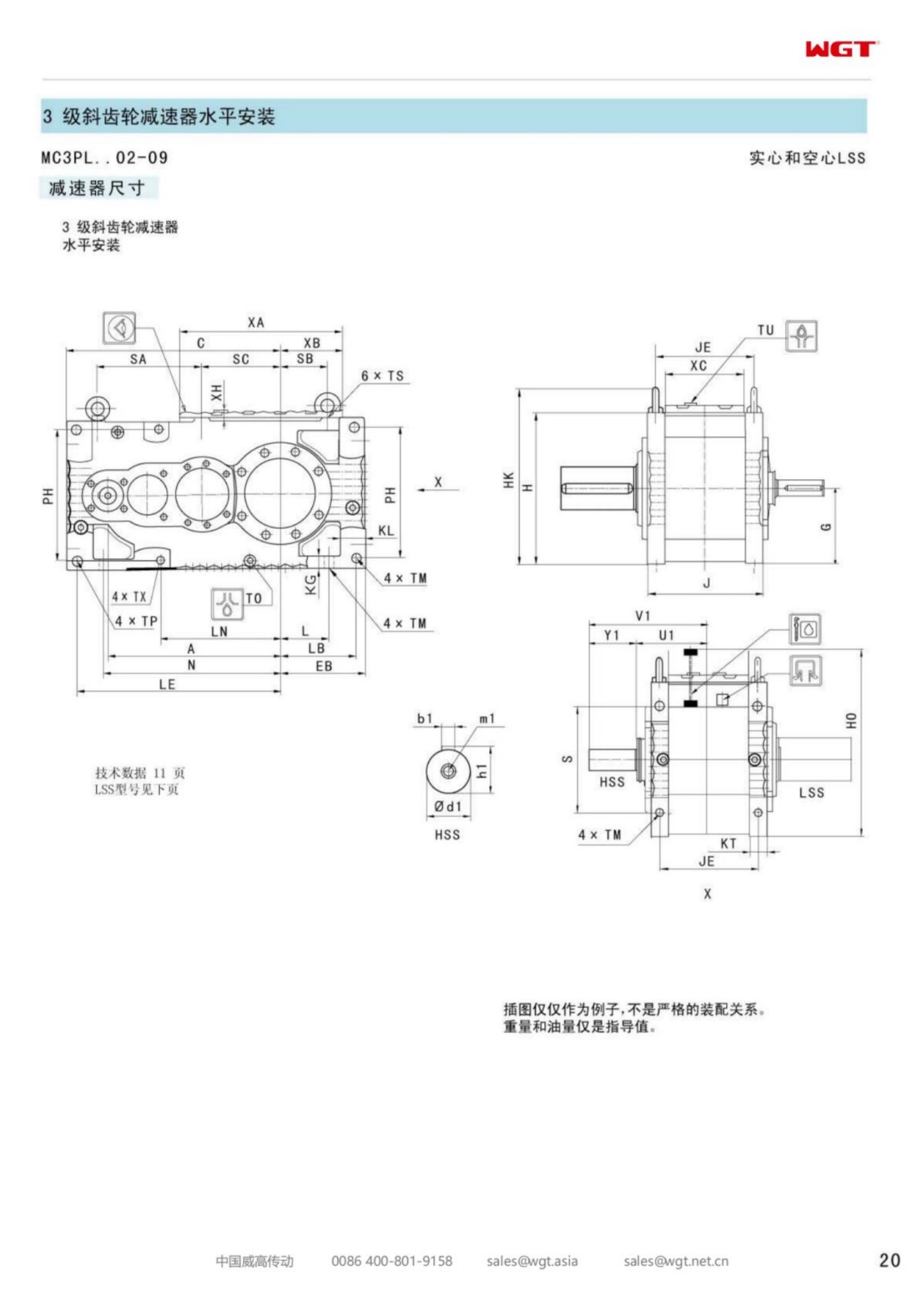
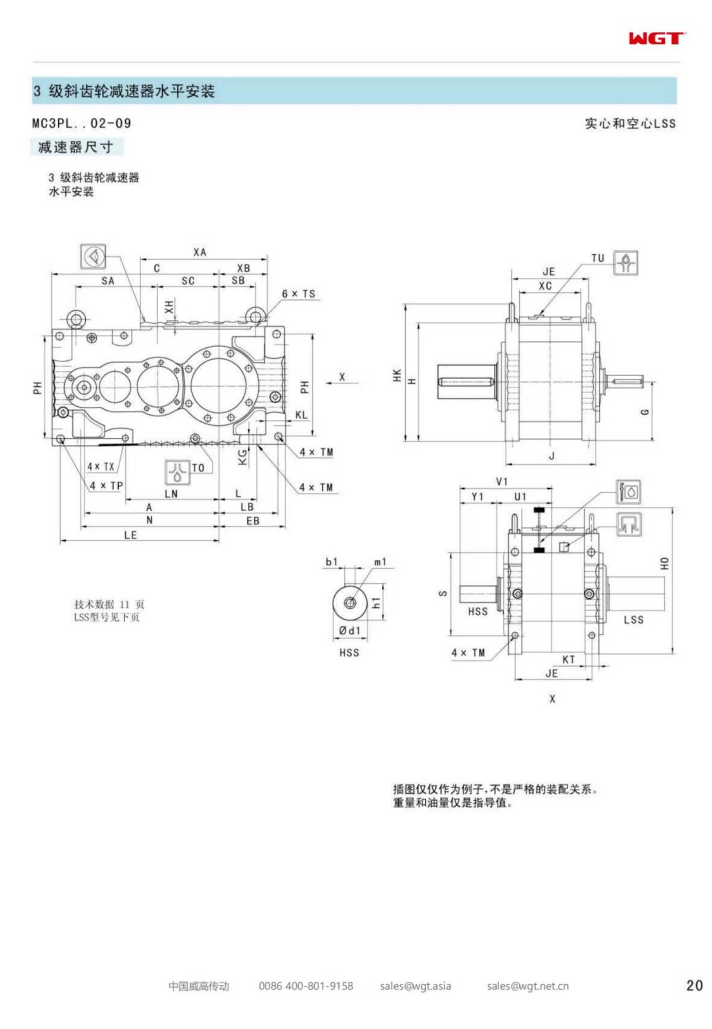
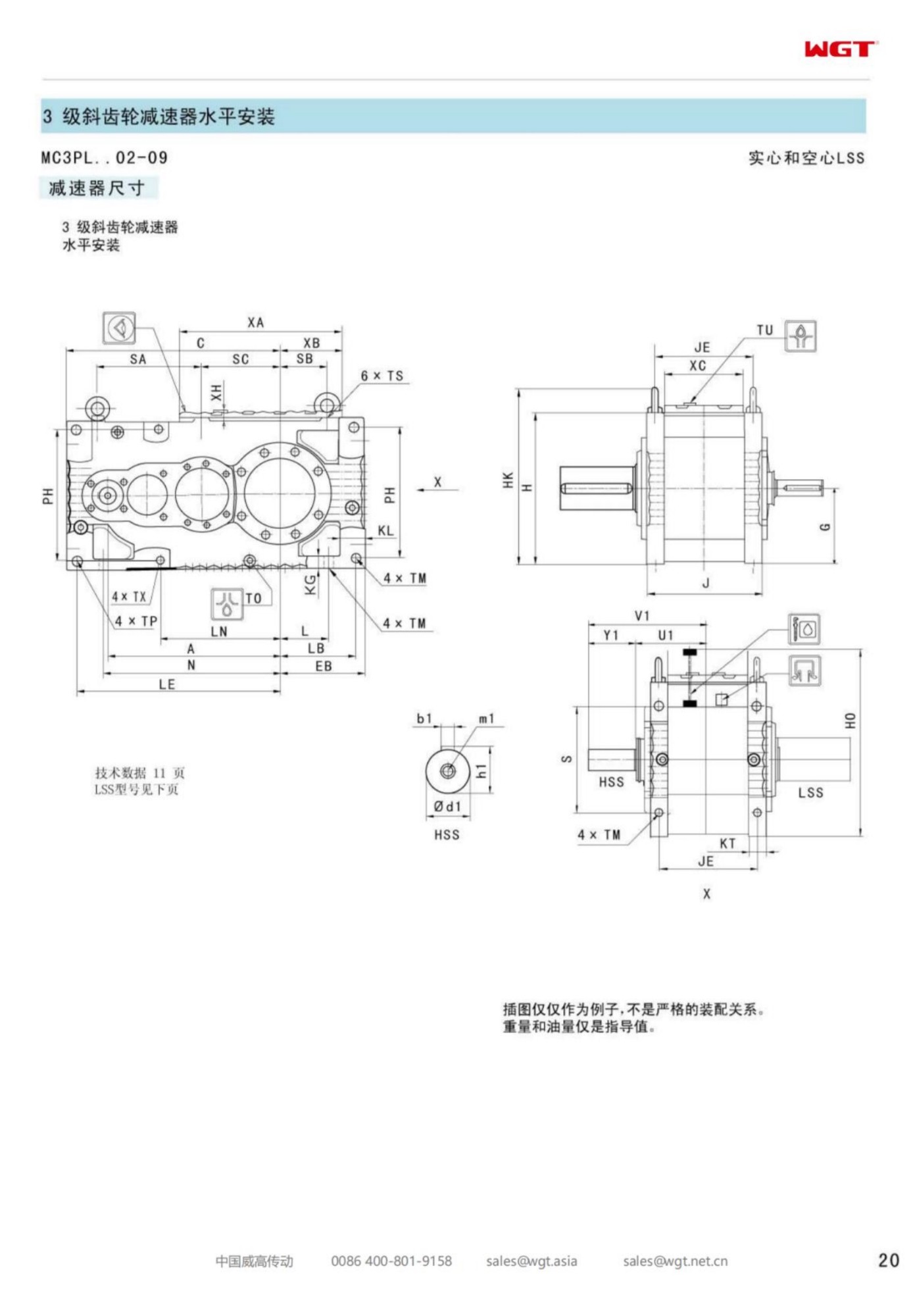
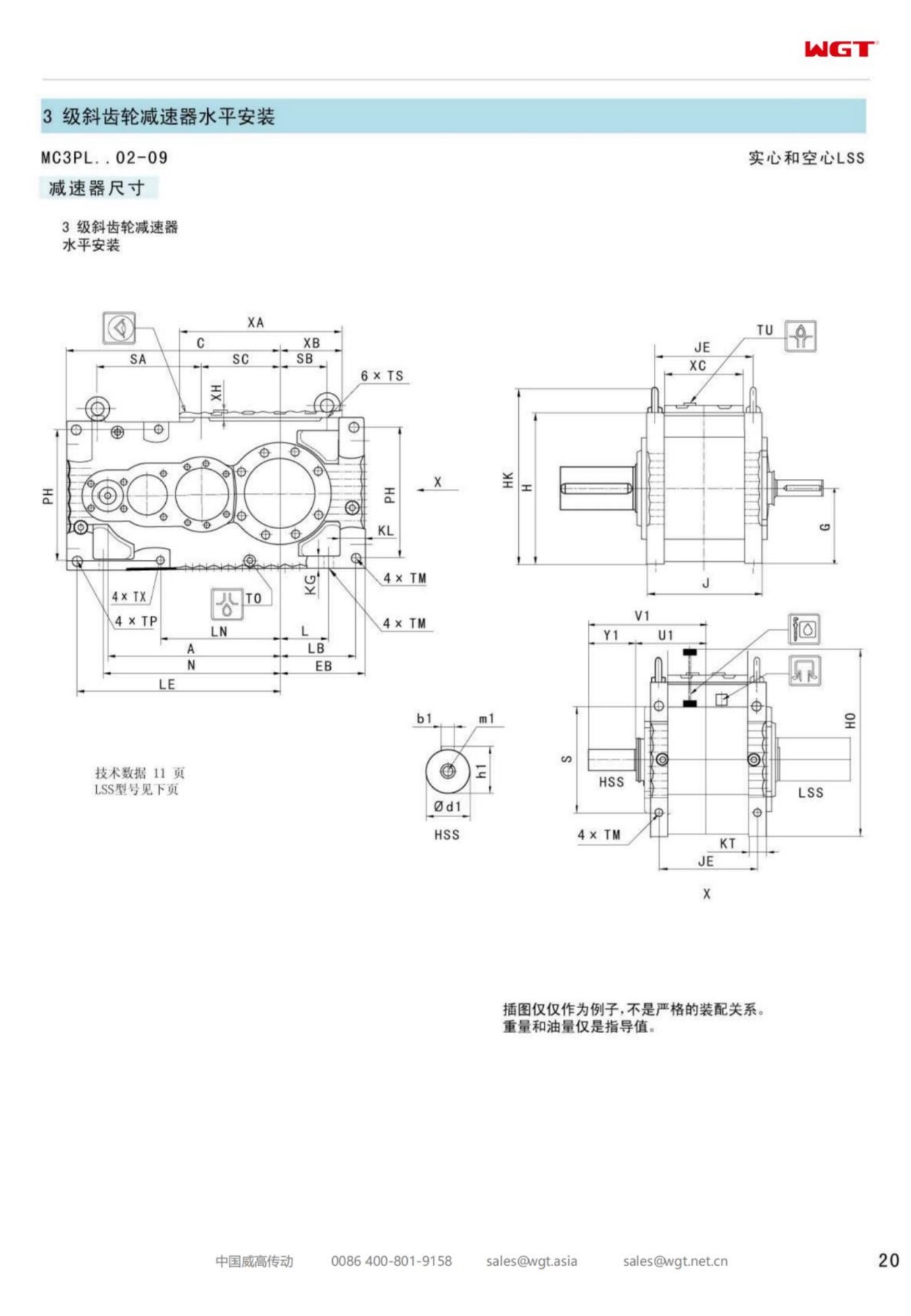
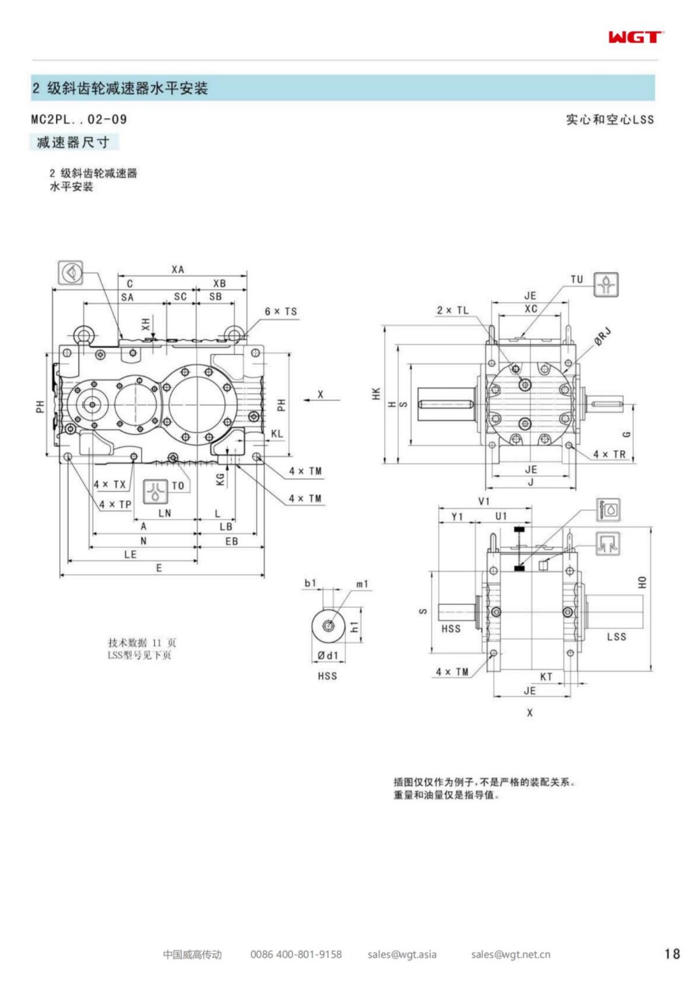
The MC2PLSF09 parallel shaft gear unit is the largest frame in this compact two-stage line, and it exists for a specific kind of enquiry: a driven machine that turns slowly, carries a very large torque, and has no tolerance for a drive that needs attention. Mills, heavy feeders, long overland conveyors and slow rotating shells all land here. The layout is unchanged from the smaller frames - helical stages in one plane, cast footed case, solid output shaft - but every dimension that carries load has been sized upward.
What Pushes a Project to the Largest Frame
Three conditions repeatedly move a selection to the top of the range. The first is torque that simply exceeds what the smaller castings can transmit with the service factor the duty demands; there is no clever way around that, the frame has to grow. The second is a starting condition far heavier than the running load, typical of a feeder that begins its shift buried in material. The third is a location where intervention is expensive - a gallery with no crane access, a plant that only shuts once a year - so the drive is deliberately given margin it will probably never use.
In each case the calculation is the same, and the answer happens to be the largest frame. That is worth saying plainly, because buyers sometimes assume the biggest unit is a commercial upsell. It is not; it is the result of the service factor arithmetic on a heavy, slow duty.
Nameplate Fields and What They Commit You To
Read the marking as a checklist against the duty sheet rather than as a part number.
| MC | Compact industrial gear unit, multi-stage helical design |
| 2 | Two stages, chosen when the ratio can be reached without a third reduction |
| P | Parallel shaft geometry, keeping the drive low and long |
| L | Heavy section case with cast feet and a large inspection opening |
| S | Solid keyed output shaft sized for the coupling of a slow, high-torque machine |
| F | Foot mounted for a horizontal bedplate installation |
| 09 | Top frame of the range, with the widest centre distance and heaviest shafts |
The two fields that never appear in the model string are ratio and mounting position, and both change the drawing. An order that omits them will be built to a default, and a default is rarely what a brownfield site needs.
Ratio Choice at Very Low Output Speeds
At the slow end, the ratio arithmetic stops being a formality. Divide motor speed by the target output speed and the result may sit beyond what two stages can deliver cleanly, which is the point where a three-stage frame or a different arrangement becomes the honest answer rather than an oversized unit running at an awkward reduction. A gearbox pushed past its natural ratio band loses efficiency and gains heat, and no amount of extra case material fixes that.
The useful discipline is to state the process speed as an absolute requirement and the ratio as a consequence, then let the selection work outward. Where a variable-speed motor is available, the ratio can be chosen for the middle of the operating band, which usually produces a smaller, cooler and cheaper unit than sizing for the slowest point alone.
Where the Biggest Frame in the Line Goes to Work
Where a through shaft and a vertical axis come together:
- Tube mill and semi-autogenous mill auxiliary drives
- High capacity overland conveyors at mine loading terminals
- Rotary dryer and cooler shell drive trains
- Ship unloader and stacker-reclaimer travel drives
- Slurry pump and thickener rake drives in tailings plants
- Heavy apron feeder and plate feeder drives at primary stations
What links these duties is not the industry but the shape of the load: slow, heavy, sustained, and expensive to interrupt. The top frame in the range is built around exactly that shape.
Levelling, Coupling Work and the Warm Re-Check
Handling a unit of this mass needs a written method before the crew arrives: certified slings on the cast lugs, a spreader where sling angles go wide, exclusion of anyone beneath the load, and a landing plan with the shims already prepared. Set the case on its pads, not on timber offcuts, and check level along both axes before the hold-down bolts are torqued in a cross pattern.
Coupling work then decides how long the seals and bearings will last. Start with a straight edge and feeler gauges for rough centring, finish with dial indicators or a laser set to the coupling maker's tolerance, and record the readings. On a slow high-torque train the warm condition is the one that matters: run under load for an hour or two and repeat the measurement, because a large driven mass shifts the alignment as it heats.
First Weeks of Running: What to Record
The first month tells you whether the selection was right, provided somebody writes down what happened. Daily: oil level against a painted mark, any change in sound. Weekly: sump temperature and bearing housing temperatures at the same points, plus a note on load. At the first oil change: the condition of the drain oil and the magnets. Taken together those three records distinguish normal running-in from a problem while the problem is still cheap.
A rising temperature trend with a steady load points at the oil, the cooling surface or the breather. A single warm bearing points at alignment or preload. Vibration that appears only in a narrow load band points at mesh contact. None of these need the unit opened to identify, and all of them are worth acting on before a shutdown is forced.
The Enquiry Sheet That Avoids a Second Round
For the top frame, the enquiry is worth more care than for a small unit because the stakes are higher. Send the motor rating, speed and starting method; the required output speed and the acceptable band around it; the absorbed torque or power at the driven machine; the duty pattern including starts per hour and whether the machine can be emptied before starting; the mounting position, available height and bedplate drawing; shaft and bore dimensions where existing hardware must be reused; ambient temperature, altitude, dust and washdown conditions; and the paint, nameplate and documentation requirements. With that in hand a frame, ratio and option set can be fixed in one exchange, and the quotation becomes something a project can order from instead of something to negotiate over.
The M3 Series at a Glance
| Model | Centre distance | Output | Typical duty |
|---|
| M3PSF50 | size 50 | solid shaft, foot | conveyors, feeders |
| M3PSF60 | size 60 | solid shaft, foot | crushers, mixers |
| M3PSF70 | size 70 | solid shaft, foot | ball mills, shredders |
| M3PSF80 | size 80 | solid shaft, foot | kilns, heavy conveyors |
| M3PSF90 | size 90 | solid shaft, foot | mill and kiln drives |
| M3RSF50 | size 50 | solid shaft, foot, right-angle | inclined conveyors, elevators |
| M3RSF60 | size 60 | solid shaft, foot, right-angle | screw classifiers, feeders |
| M3RHF70 | size 70 | hollow shaft, foot, right-angle | agitators, drum drives |
| M3PHT80 | size 80 | hollow shaft, torque arm, parallel | shaft-mounted conveyors |
| M3RHT90 | size 90 | hollow shaft, torque arm, right-angle | heavy shaft-mounted drives |
All frames in the table belong to one industrial family. P = helical parallel-shaft, R = bevel-helical right-angle; the low-speed shaft is solid (S) or hollow (H), mounted on feet (F) or a torque arm (T).
Selection Example: Heavy apron feeder at a primary crushing station
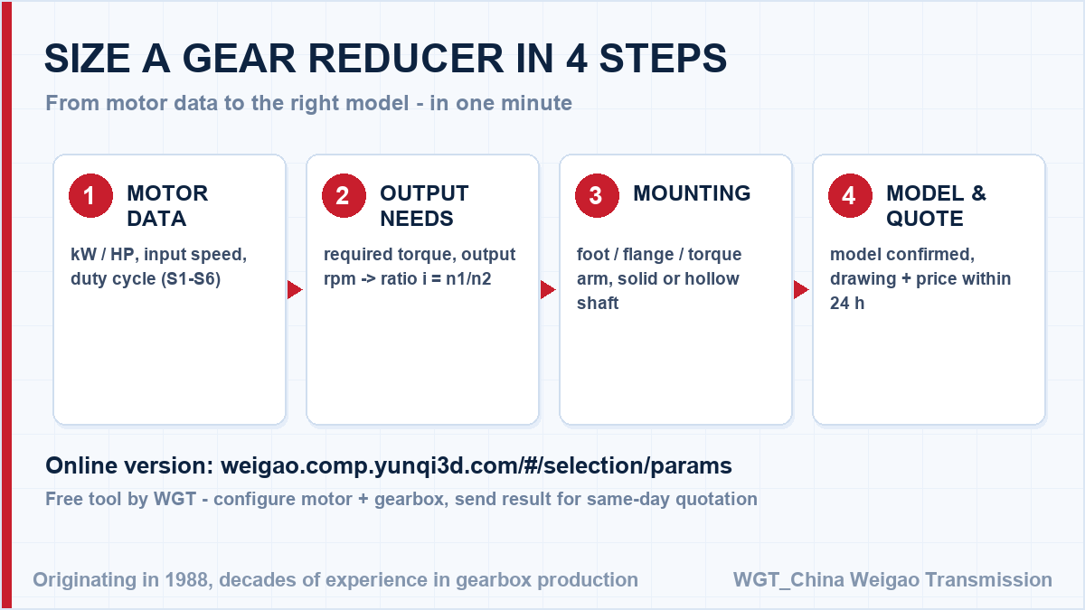
Take a 990 rpm six-pole motor turning the feeder head shaft at 9 rpm. The ratio follows directly: 990 / 9 = 110, which sits in the deeper end of the two-stage band and needs the breakaway torque of a feeder buried in material rather than the running load. In this case the top frame in the range carries that starting moment with margin, which is why it is chosen for stations where a stalled feeder stops the whole plant. That single division gives the catalogue ratio; the service factor for your duty class is then applied to the torque, and the frame size follows.
![how to size a industrial helical gearbox in four steps]()
Sizing flow: motor speed, target output speed, torque, service factor.
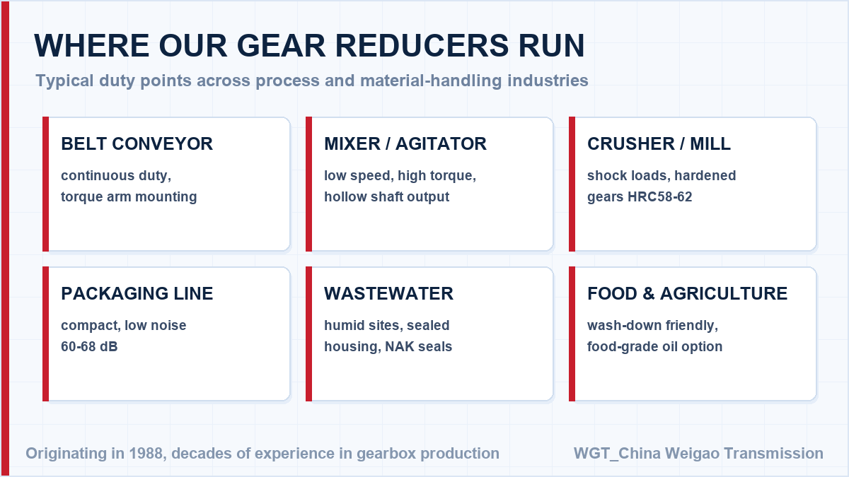
Where This Series Works in Practice
Cement plant clinker belt
A cement plant drives its clinker transport belt with reducers in dusty, high-ambient conditions. Sealed housings and a 40 deg C maximum temperature rise let the units sit close to the kiln without extra cooling.
Paper mill pulp agitator
A paper mill uses reducers on pulp chest agitators. Continuous 24-hour duty is handled by lifetime lubrication, and the low backlash keeps the agitator steady when the stock consistency changes.
Technical Questions, Answered
Which lubrication system does the unit use?
Small and medium frames run on splash lubrication with mineral or synthetic oil. Larger frames or high ambient temperatures can be ordered with forced-feed circulation and cooling coils; the lubricant grade is stated on the nameplate and in the manual.
How often should the oil be changed in heavy duty?
With mineral oil, plan an initial change after the running-in period and then roughly every 5,000 hours. Synthetic oil stretches the interval to around 10,000 hours. Hot environments, dust or frequent starts shorten the interval - we advise the schedule with the quotation.
![industrial helical gear reducer application fields]()
Common application areas for right-angle industrial helical drives.
Duty Data In, Firm Model Out
Three numbers decide it. Skip the back-and-forth: configure your drive in the WGT Motor & Gearbox Online Selection System and send us the result for a same-day quotation.
Motor power and speed, required output speed and the driven-machine description fix the selection. Send them and the confirmed model, service factor and price come back in writing the same day. Looking for a gear reducer for food processing machine? Tell us the duty point and we will confirm the model in writing.