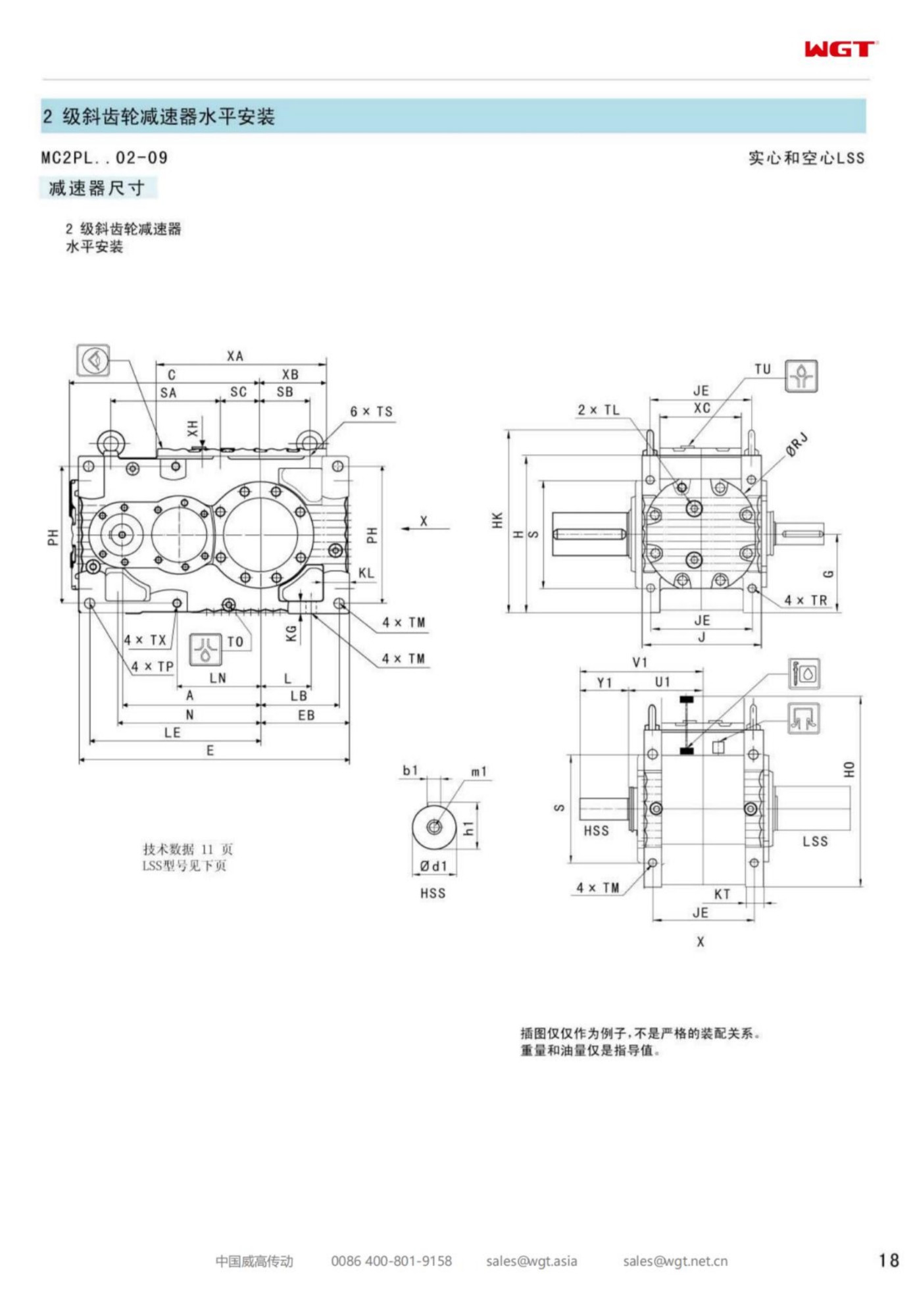
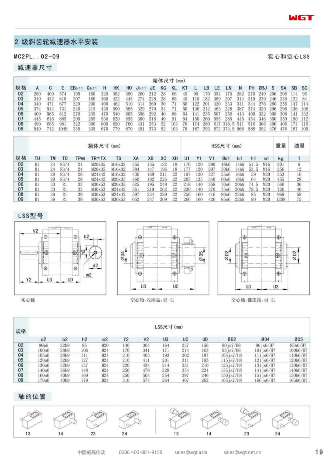
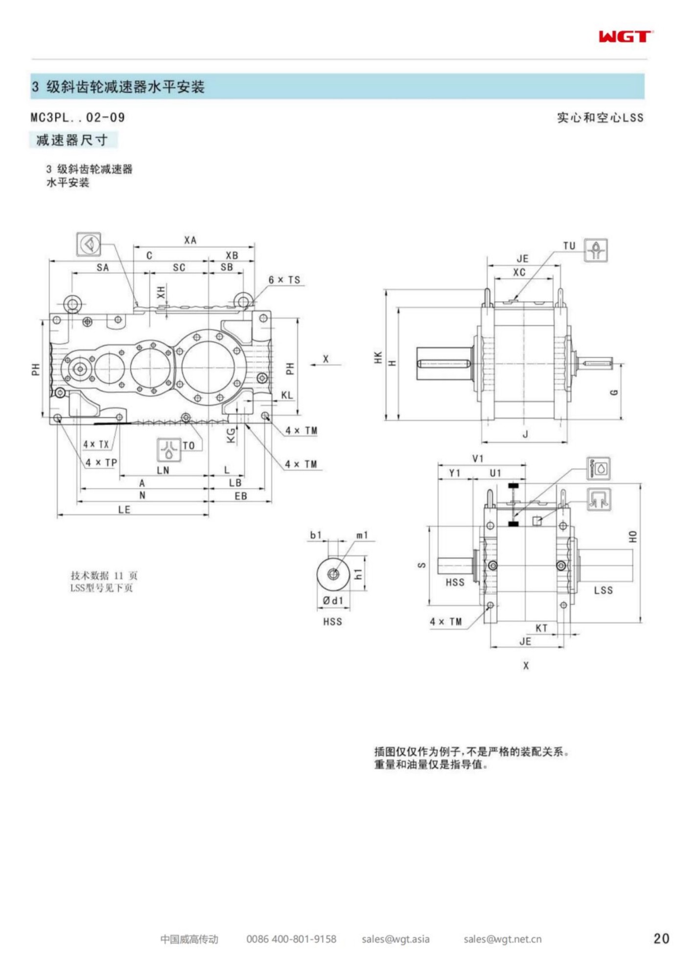
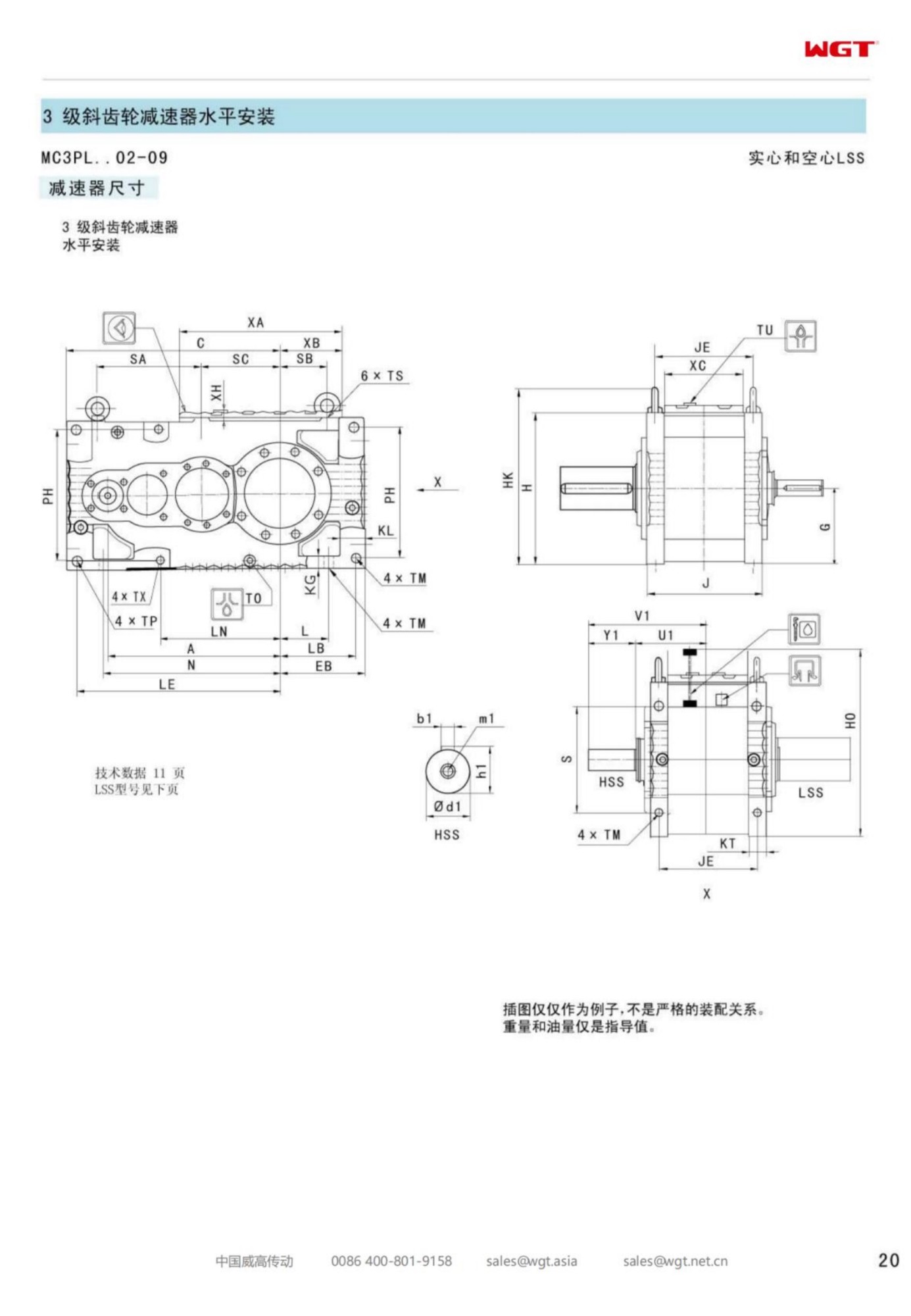
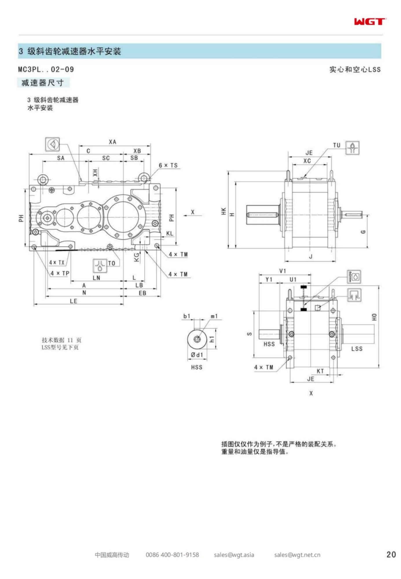
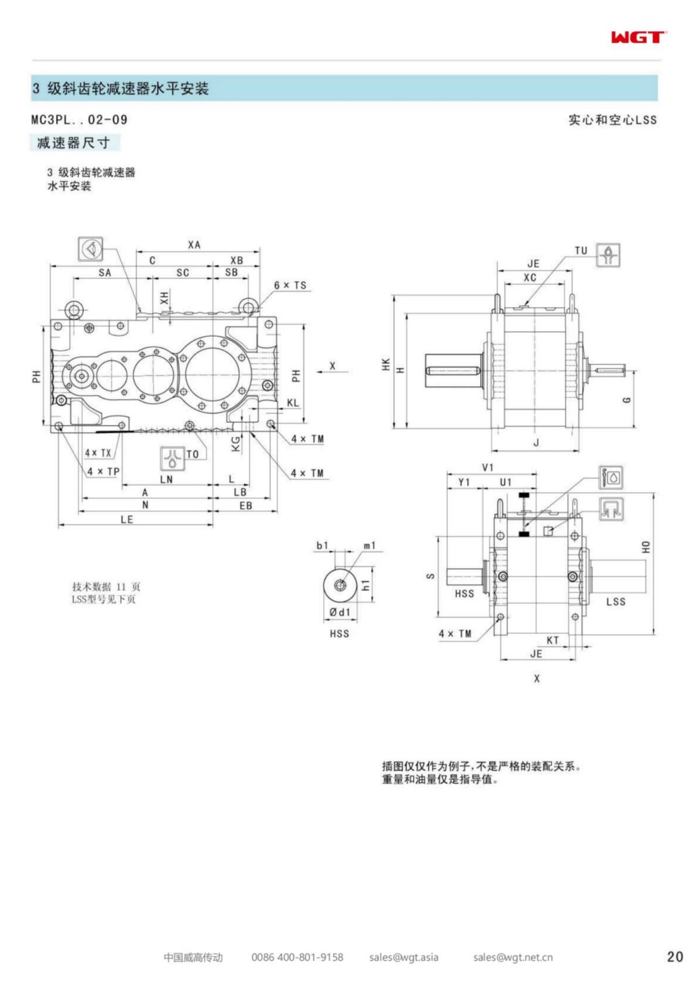
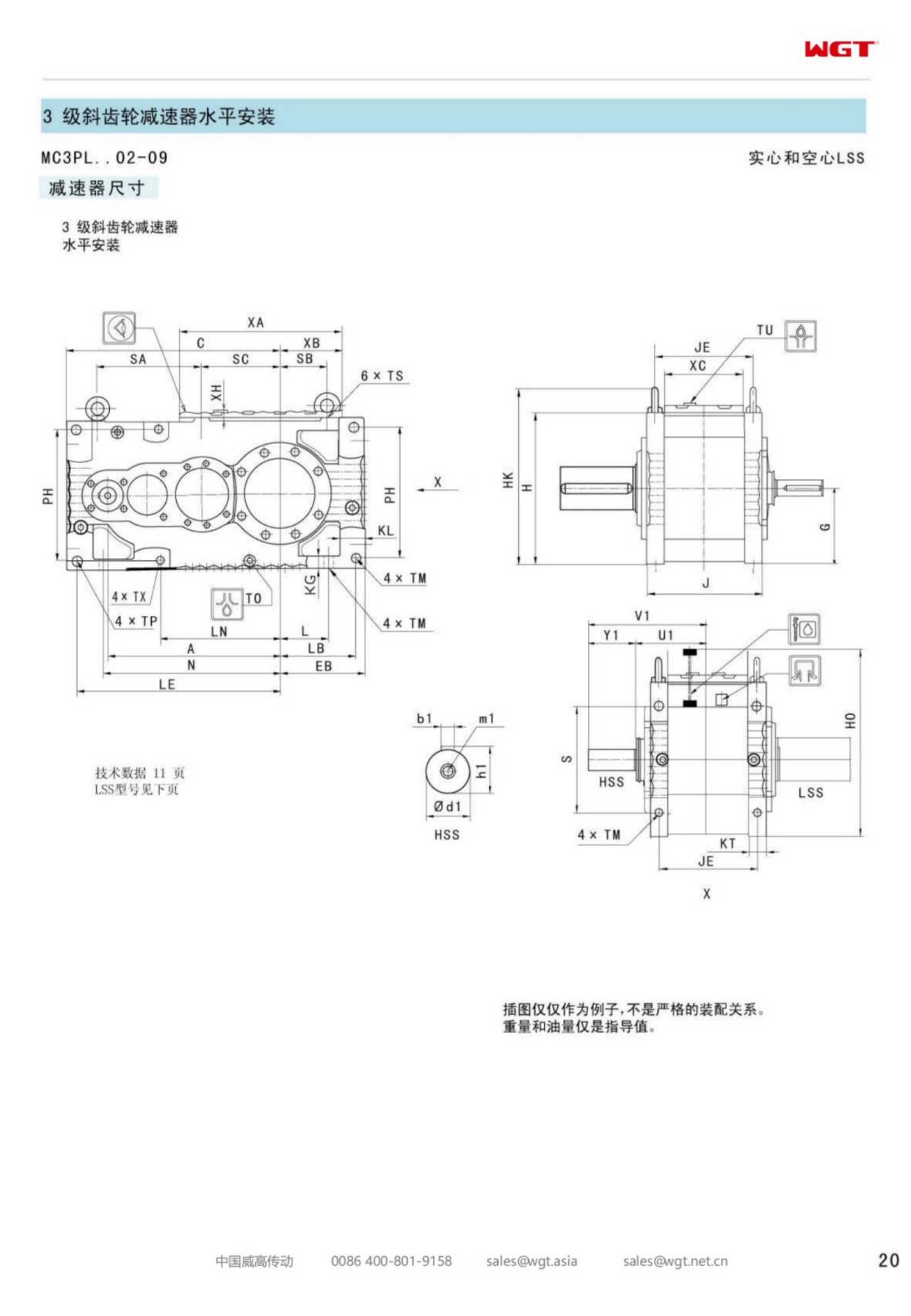
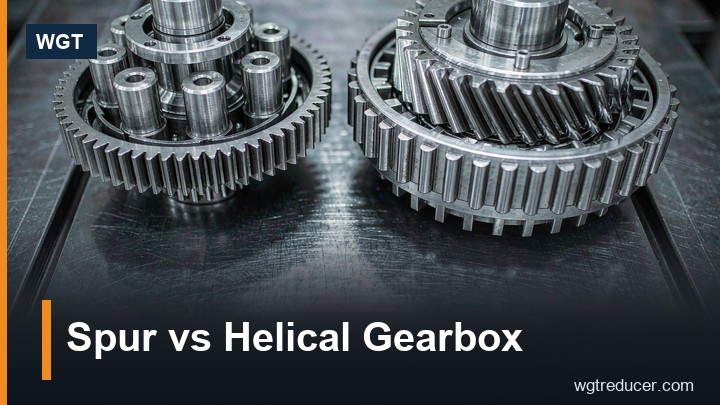
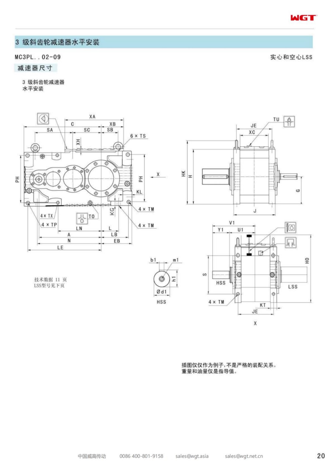
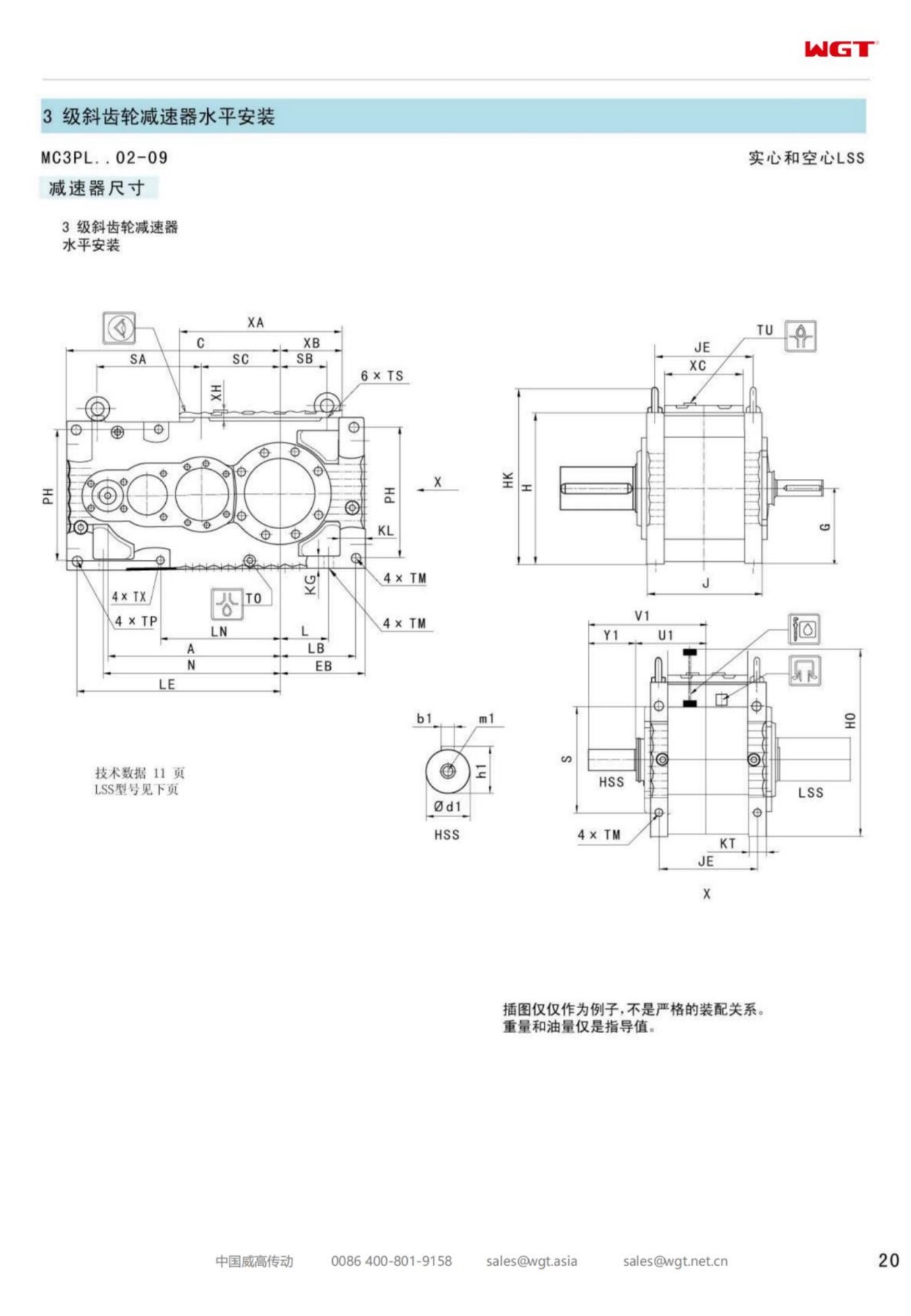
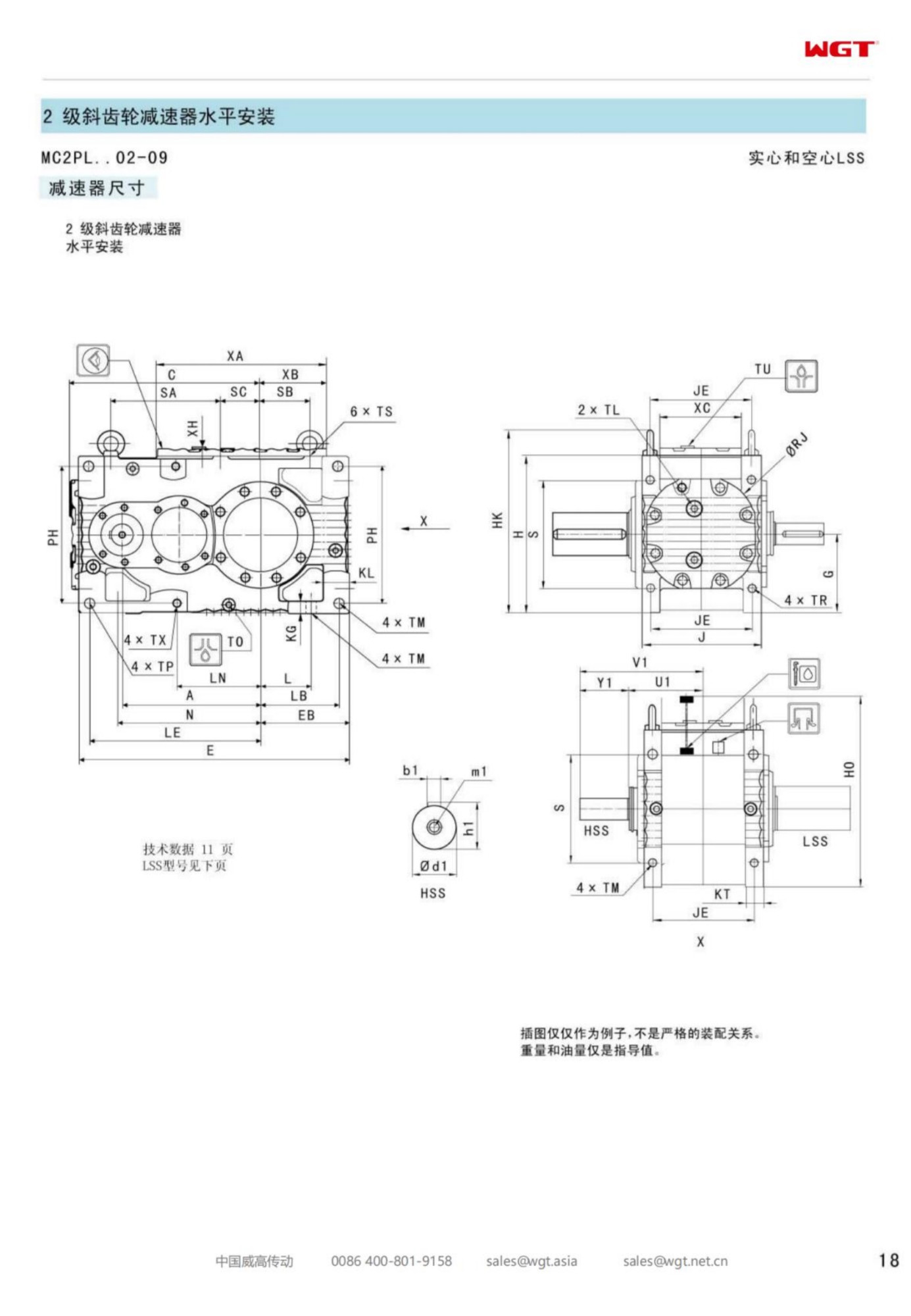
Shaft-mounted families earn their reputation on the hollow-bore models, because hanging a gearcase straight over the driven shaft is the fastest installation a plant can buy. Yet a curious number of orders in every band are placed for the solid-shaft frames instead. The reason is never fashion. It is that a coupling between the gearcase and the machine solves three problems a bore cannot touch, and the MC2PLST02 solid shaft gearbox is the small-to-mid frame in this band where those problems begin to dominate the selection meeting.
The construction keeps everything the family is known for - two helical stages in a level case, an arm handing the reaction to the structure, no bedplate and no foundation - and swaps the one detail that defines the installation: the output leaves the case as a solid shaft, and a coupling carries the torque across the last metre to the machine. That last metre is where most of this page lives, because a coupled drive changes the alignment story, the guarding story and the story about what the plant actually knows about its own driven shaft.
Why a Solid Shaft Changes the Conversation
A bore-over-shaft installation makes an assumption: that the shaft already in the machine is sound, measured, and worth building a drive around. When that assumption holds, nothing beats the arrangement. When it does not - an old conveyor whose head shaft has worn at the bearing journals, a machine whose shaft was turned down years ago after a failure, a duty where nobody is sure what is actually under the paint - building a new frame onto that shaft transfers the old shaft's history into the new gearbox's warranty period.
A solid-shaft frame breaks that dependency. The gearcase bolts to a bracket, the torque arm takes the reaction, and the connection to the machine is a coupling chosen for the duty. The old shaft can be sleeved, re-turned, fitted with a new hub or cut back and re-ended without the gearcase caring, because the interface is a standard bore in a standard hub rather than a machined fit on a specific shaft. For plant engineers who have been burned once by a shaft they were told was fine, that separation is the whole argument.
Decoding MC2PLST02
The type string reads field by field, as across the whole band, and the final digit places the frame inside it.
| MC | Industrial gear unit family for continuous plant service |
| 2 | Two helical reductions in a single gear plane |
| P | Parallel-shaft layout, input and output parallel |
| L | Level build, both shafts horizontal in one case |
| S | Solid output shaft leaving the case through a conventional coupling |
| T | Torque arm reaction, no feet and no foundation |
| 02 | Second frame: the step where coupled drives and weak existing shafts set the specification |
As an ordering document the string fixes geometry and leaves the engineering to the lines around it: ratio, service factor, the coupling type and size, the brake or backstop if the duty needs one, and the bracket drawing. A buyer who sends the string alone will receive a correct gearcase and guess at everything that makes it a working installation.
The Coupling Is Part of the Gearbox
On a bore-over-shaft frame there is no coupling, so there is no coupling discussion. On a solid-shaft frame the coupling sits in the torque path on every revolution of the machine's life, and treating it as an accessory rather than a component is the most common way a good frame ends up in a bad year. The choice is not exotic. Flexible element couplings in elastomer or gear form both serve; what matters is that someone chose the size on transmitted torque with the service factor applied, checked the bore range against the actual shaft, and decided whether the element type suits the duty's starts, reversals and temperature.
The second decision is the hub fixing. Parallel keys remain the default and are entirely satisfactory when the keyway is cut to standard and the hub is fitted correctly. Taper bushings buy faster assembly and removal at the price of a component whose condition matters, and they deserve a mention in the maintenance documents rather than being discovered by whoever has to remove the coupling in year six. Either way, the coupling specification belongs in the order, not in the site stores' interpretation of what was probably intended.
Where the Hollow Bore Loses
It is worth stating plainly where the bore-over-shaft arrangement is the wrong answer, because those are exactly the duties a solid-shaft frame exists for. First, when the driven shaft's history is unknown or unflattering - a re-welded journal, a shaft with a known past overload, a fit surface that measures outside tolerance. Second, when the machine needs something in the torque line that a bare shaft cannot host: a brake disc, a torque limiter, a flywheel, an inspection coupling. Third, when the plant wants the gearcase and the machine separable by two hub bolts for a fast unit exchange instead of a bore withdrawal that needs clearance along the shaft and a planned press off.
Fourth, and less discussed: when the driven shaft is short. A bore needs enough shaft length to carry the case plus clearance to slide it on. Machines with stub shafts, shafts ending against a bearing housing, or shafts shared with a second machine cannot accept a bore at any price, and no amount of adaptation makes one fit. The solid shaft with a coupling is not the second choice in those duties; it is the only choice.
Alignment With a Flexible Coupling in the Line
A flexible coupling forgives a great deal, which is precisely its danger. The element tolerates misalignment that the bearings on both machines quietly pay for, so a coupled drive installed by eye will run - sometimes for years - while the gearcase and the machine consume bearing life at a rate nobody has anything to compare against. The discipline is small and known: set the gearcase level on its bracket, check angular and parallel alignment to the coupling maker's figures with a dial indicator or laser, and record the numbers on the commissioning sheet so the next crew has a baseline.
Re-checking matters more on this construction than on most. The torque arm holds the case against the reaction, and anything that moves the bracket - foundation settlement, a loose arm pin, a bumped guard - moves the alignment with it. A five-minute alignment check at every planned stop is cheaper than a bearing failure it prevents, and the check doubles as an inspection of the arm hardware that the frame's whole mounting concept depends on.
Guards and the Space Around a Coupled Drive
The bore-over-shaft arrangement has no exposed rotating joint, and that is one of its quiet virtues. A coupled drive has a spinning coupling and shaft end, so guarding becomes part of the installation rather than an afterthought. The guard needs to come off for coupling service and go back on without a fight, which argues for a split design with real fasteners rather than a wrapped sheet held by hope. It also needs to keep hands and clothing out while admitting air, because an enclosed elastomer element in a hot corner ages faster than the same element in free air.
Space planning belongs at order time. A coupling adds length to the drive line, and the machines built around a bore-mounted gearbox sometimes have no metre to spare. Measuring the gap between the gearcase face and the machine, and confirming the coupling's installed length plus removal clearance, takes ten minutes and prevents the classic site improvisation of packing the bracket out and inventing an alignment problem that did not exist before.
Backstops and Brakes on a Coupled Line
Inclined duties ask what stops the load when the power stops, and a coupled line answers with more options than a bore ever could. A backstop can live inside the gearcase, on the motor, or as a standalone unit in the coupling line; a brake disc can ride the coupling and take a caliper from either side. The plant's own preference - what its crews know how to maintain, what spares it already carries - is a legitimate selection criterion, and it is only available when there is a coupling to hang things on.
What the order needs is the question asked in plain words. Does the conveyor run back, has it ever, what holds it today, and does the plant want the holding device where the next crew can reach it? A duty specified without that conversation discovers its answer during the first power dip, and the repair that follows is always larger than the coupling line item would have been.
Duty Profiles That Belong on Frame Two
Coupled drives where the driven shaft cannot be trusted and the coupling does the work:
- Head drive of an inclined bagging conveyor at a fertiliser blending plant
- Bucket elevator drive on a grain terminal leg with the backstop in the coupling
- Belt feeder under a crushed-limestone stockpile at an aggregate quarry
- Drag chain conveyor drive in a wood pellet store
- Screw conveyor drive at a flour mill blending house
- Cleated transfer conveyor at a salt processing and packing site
What these positions share is a torque in the band's light-to-mid range and a reason - shaft, access, or an accessory in the line - that a bore cannot serve. The frame does the work; the coupling makes the installation possible at all.
Same Torque Arm, Different Tail
The mounting logic is the family standard and is worth restating because coupled drives sometimes drift into bedplate thinking. The gearcase hangs on a bracket; the arm takes the reaction into the structure; nothing is grouted and nothing needs a foundation. What changes with the solid shaft is the tail of the installation: the bracket positions the case so the coupling lines up, and the shimming of that bracket is now alignment work rather than cosmetics.
Two practical habits follow. Bolt the bracket with fasteners that can be re-torqued, not welded into a position nobody can adjust. And leave the shims in place, labelled, so the alignment check at the next stop starts from the recorded geometry instead of from zero. The arm's bushings and pins go on the inspection list with the same seriousness as the coupling element, because a worn arm joint moves the case by fractions that the coupling forgives and the bearings do not.
Surveying the Driven Shaft Before You Order
The ironies of a solid-shaft order are worth naming: the coupling frees the gearcase from the old shaft's condition, but the coupling still has to grip something, so the shaft deserves a measurement before the order rather than a diagnosis after. Diameter at the hub position, runout at the same point, keyway width and depth, and an honest note of any previous repair - sleeving, build-up weld, a turned-down section - because all of them change the hub selection and the fit class.
Photograph the shaft and send the numbers with the enquiry. The difference between a hub ordered for a measured shaft and a hub ordered for a nameplate guess is one site visit nobody budgeted, and on some duties it is a second visit when the first set of bushes does not seat. The survey also settles the coupling length question against the actual gap, which is the other measurement that turns an installation into a two-hour task instead of a two-day one.
Living With a Coupled Drive
Day-to-day, a coupled frame asks for three things and no more. The coupling element goes on the spares shelf, one unit per critical drive, because it is the only part in the torque path that is designed to wear. The guard comes off at each planned stop for a look at the element, the hub fixings and the arm hardware. And the alignment gets a number recorded against it every time, so drift shows up as a trend instead of as a failure.
The oil side is unchanged from the rest of the family: level checked on a schedule, first change early, samples read as a trend. The discipline that separates well-run coupled drives from poorly-run ones is almost entirely on the coupling side of the case, which is where the site's habits - good or bad - are written into the machine's life.
Ordering a Solid-Shaft Frame
The enquiry that gets this frame right reads like the family standard with four additions. The driven shaft measured and photographed, its history stated honestly. The gap between gearcase face and machine, so the coupling length is chosen rather than discovered. The accessory question - brake, backstop, limiter, flywheel - answered for the duty, not deferred to the site. And the plant's coupling preference, if it has one, so the order arrives with spares the stores already understand.
Sent that way, the frame arrives as an installation: gearcase, arm, coupling, guard drawings, and a commissioning checklist that matches what the crew will actually touch. The same frame ordered on kilowatts alone still runs, but it runs on a coupling chosen by whoever was nearest the stores counter, and the alignment was set by eye. Both of those costs arrive later, in the maintenance budget, where they are much harder to explain.
Selection Example: Head drive of an inclined bagging conveyor at a fertiliser blending plant
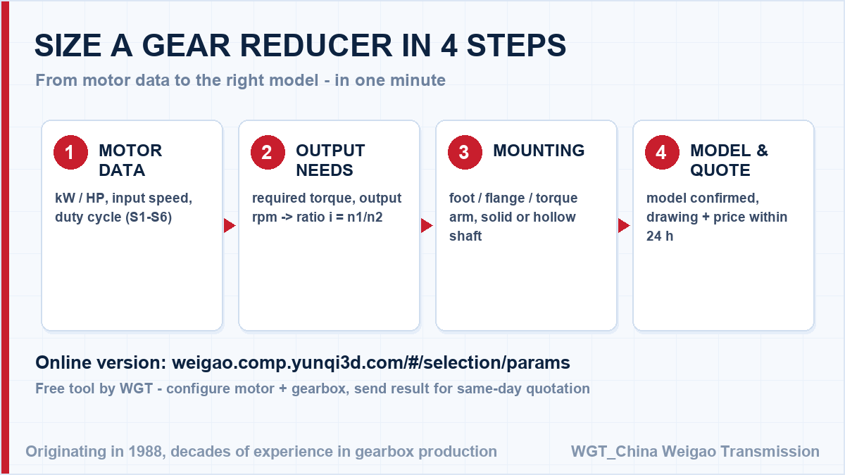
Take a 22 kW motor at 1470 rpm turning the head shaft at 42 rpm. The ratio follows directly: 1470 / 42 = 35, so a ratio near i=35 comes out of the two-stage band, and the frame is chosen with margin for the starts an elevator leg and its backstop add. In this case frame two carries the duty with the coupling hosting the backstop, and the torque arm bolts to a bracket the structure already has. The same three numbers - motor speed, target output speed, required torque - are all you need; our engineers (or the online selector below) cross-check the service factor for your duty cycle.
![gear reducer selection flow chart - ratio and frame size]()
Figure: from motor data to a confirmed gearbox model in four steps.
Common Models in the M3 Series
| Model | Centre distance | Output | Typical duty |
|---|
| M3PSF50 | size 50 | solid shaft, foot | conveyors, feeders |
| M3PSF60 | size 60 | solid shaft, foot | crushers, mixers |
| M3PSF70 | size 70 | solid shaft, foot | ball mills, shredders |
| M3PSF80 | size 80 | solid shaft, foot | kilns, heavy conveyors |
| M3PSF90 | size 90 | solid shaft, foot | mill and kiln drives |
| M3RSF50 | size 50 | solid shaft, foot, right-angle | inclined conveyors, elevators |
| M3RSF60 | size 60 | solid shaft, foot, right-angle | screw classifiers, feeders |
| M3RHF70 | size 70 | hollow shaft, foot, right-angle | agitators, drum drives |
| M3PHT80 | size 80 | hollow shaft, torque arm, parallel | shaft-mounted conveyors |
| M3RHT90 | size 90 | hollow shaft, torque arm, right-angle | heavy shaft-mounted drives |
The table below shows the M3 industrial range: P builds are all-helical on parallel axes, R builds add a bevel input stage for a right-angle drive; S / H describe the low-speed shaft and F / T the mounting.
Application Cases
Coal handling conveyor
A power station coal-handling plant standardized on one industrial gear family for thirty drives. A single spare-part pool now covers the whole conveyor network, from transfer points to the bunker feed.
Dredger pump drive
A dredging contractor powers its slurry pump skid with an industrial gear unit built for shock loads. The dense abrasive mixture demands a rigid drive train, and ground gearing has kept backlash unchanged over multiple seasons.
![industrial gearbox applications - conveyor mixer crusher wastewater]()
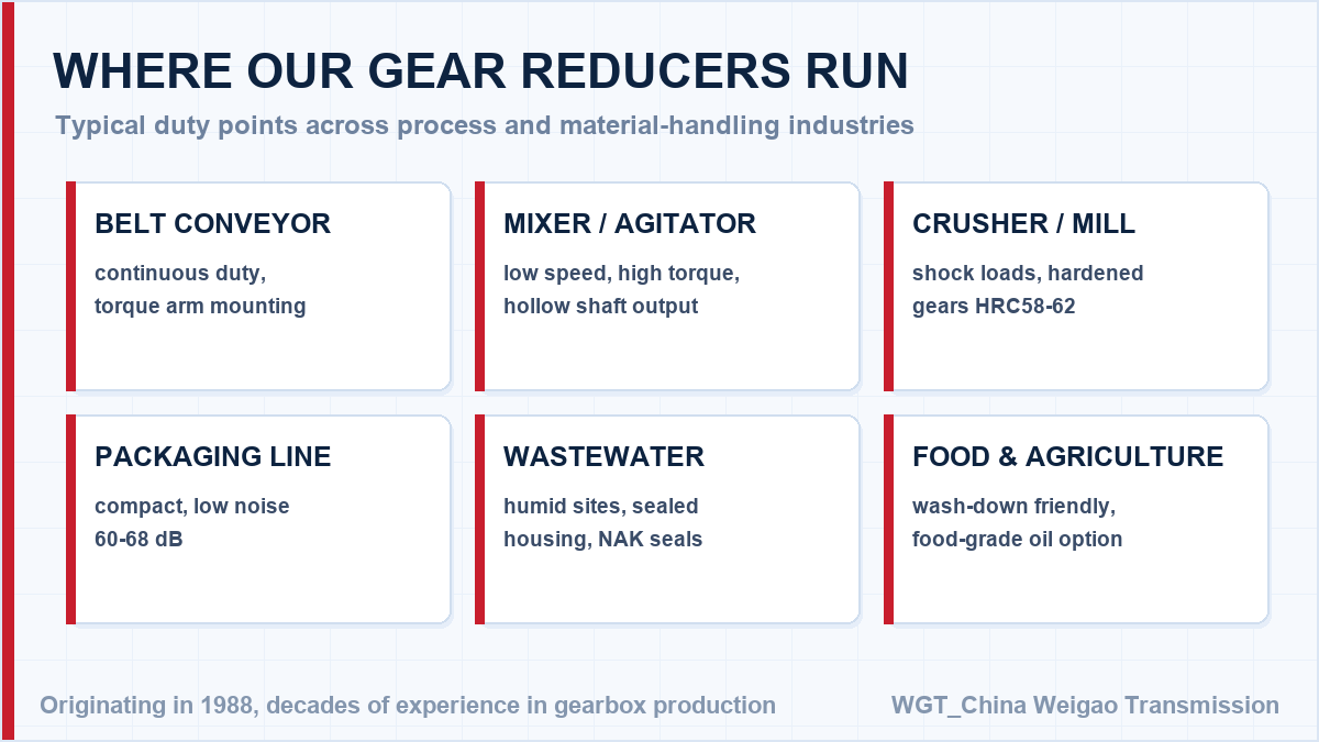
Figure: typical industries that use the WGT S-series gear reducers.
Frequently Asked Questions
Which lubrication system does the unit use?
Small and medium frames run on splash lubrication with mineral or synthetic oil. Larger frames or high ambient temperatures can be ordered with forced-feed circulation and cooling coils; the lubricant grade is stated on the nameplate and in the manual.
How often should the oil be changed in heavy duty?
With mineral oil, plan an initial change after the running-in period and then roughly every 5,000 hours. Synthetic oil stretches the interval to around 10,000 hours. Hot environments, dust or frequent starts shorten the interval - we advise the schedule with the quotation.
Can the unit be rebuilt instead of replaced?
Yes. Bearings, seals and gear sets are available as spare internals, and the horizontally split housing allows inspection and reassembly on site. Many operators overhaul units during annual shutdowns instead of buying new.
Send the Nameplate - Get the Equivalent Frame
Matching an existing installation? Not sure which model fits? Try our online WGT Motor & Gearbox Online Selection System to match motor power, ratio and mounting in one minute.
Photograph the nameplate or note the model and ratio. We identify the equivalent frame, confirm the torque margin and return a quotation with the outline drawing - usually within one working day. Looking for a gearbox for agricultural machine? Tell us the duty point and we will confirm the model in writing.