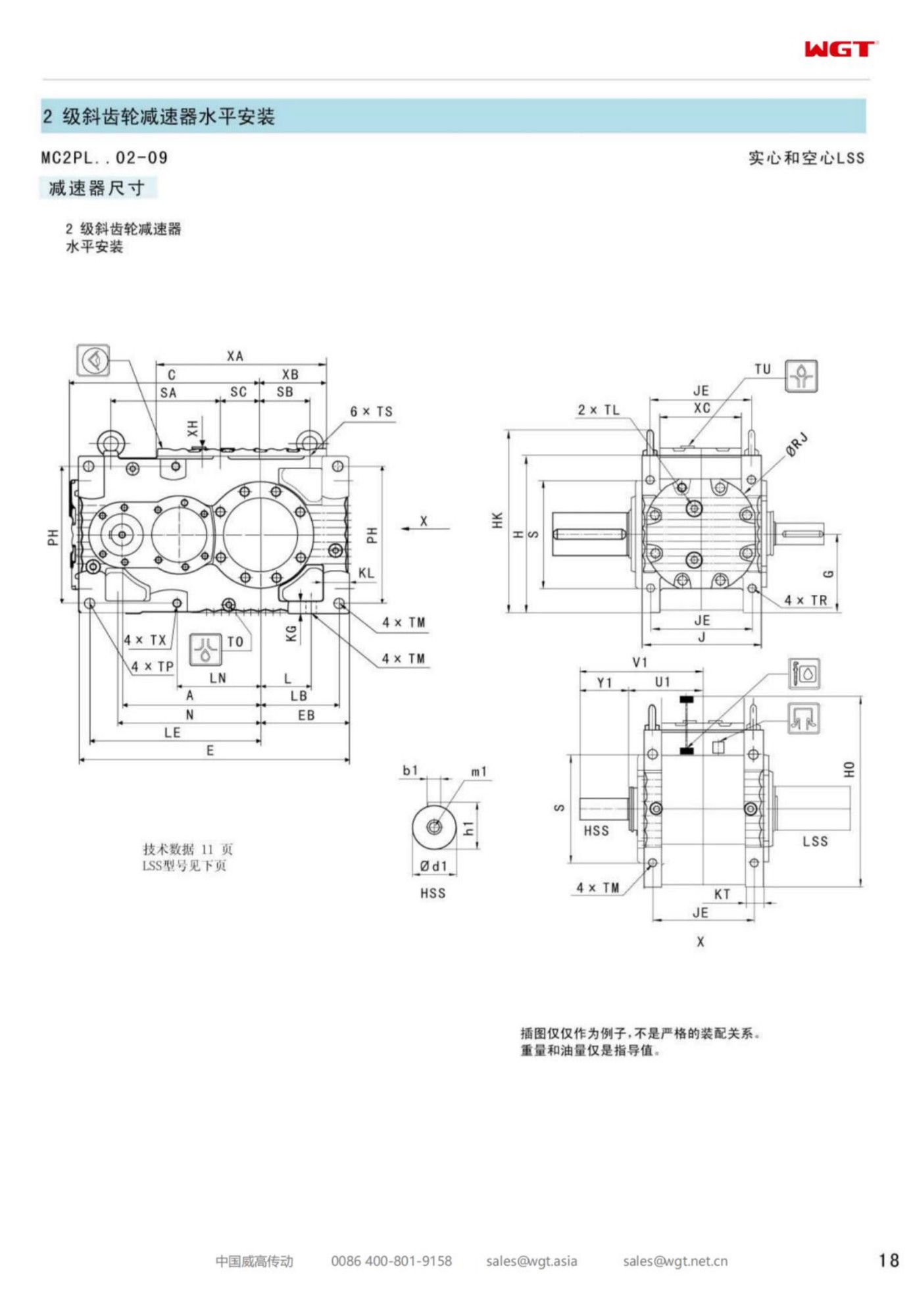
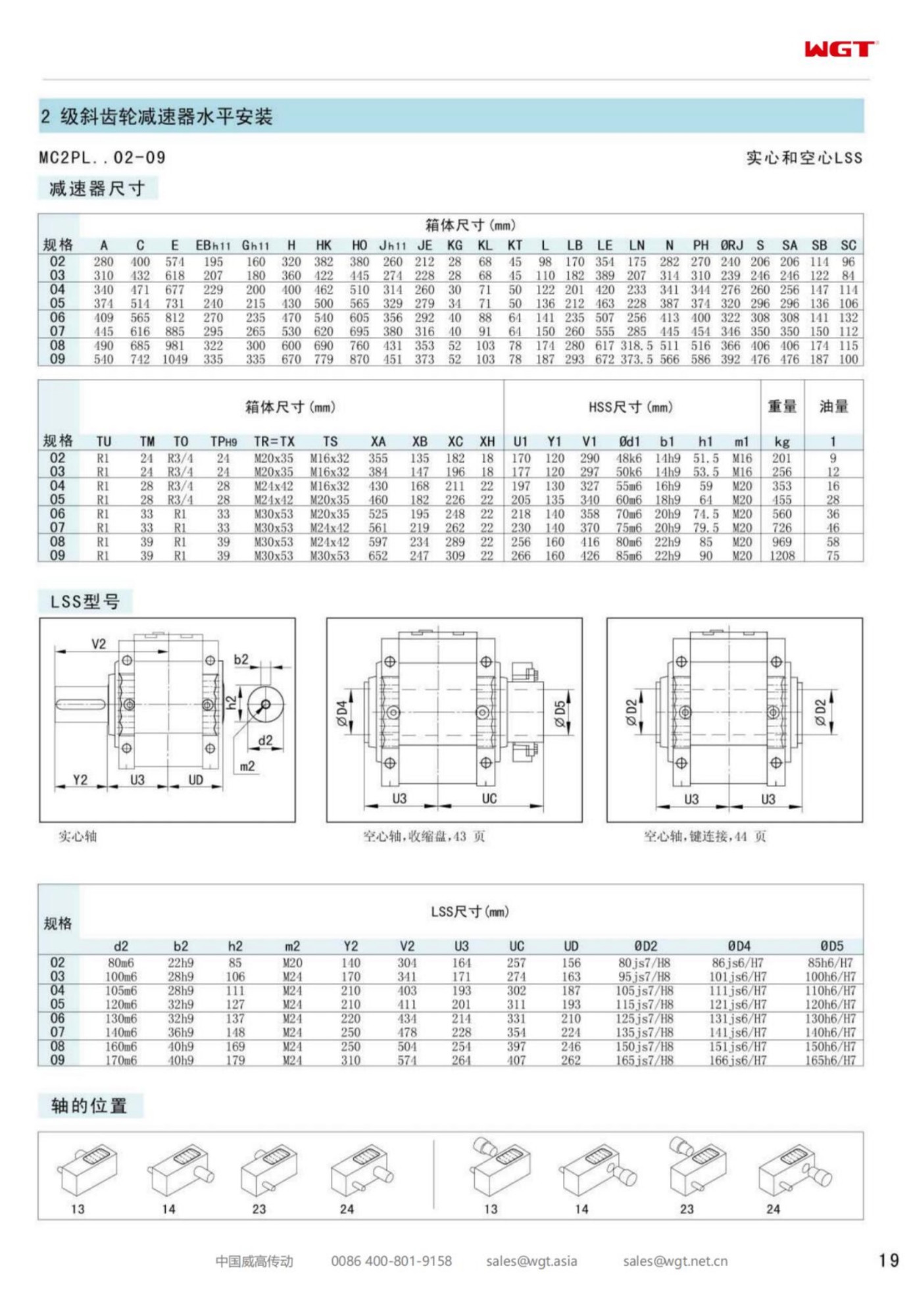
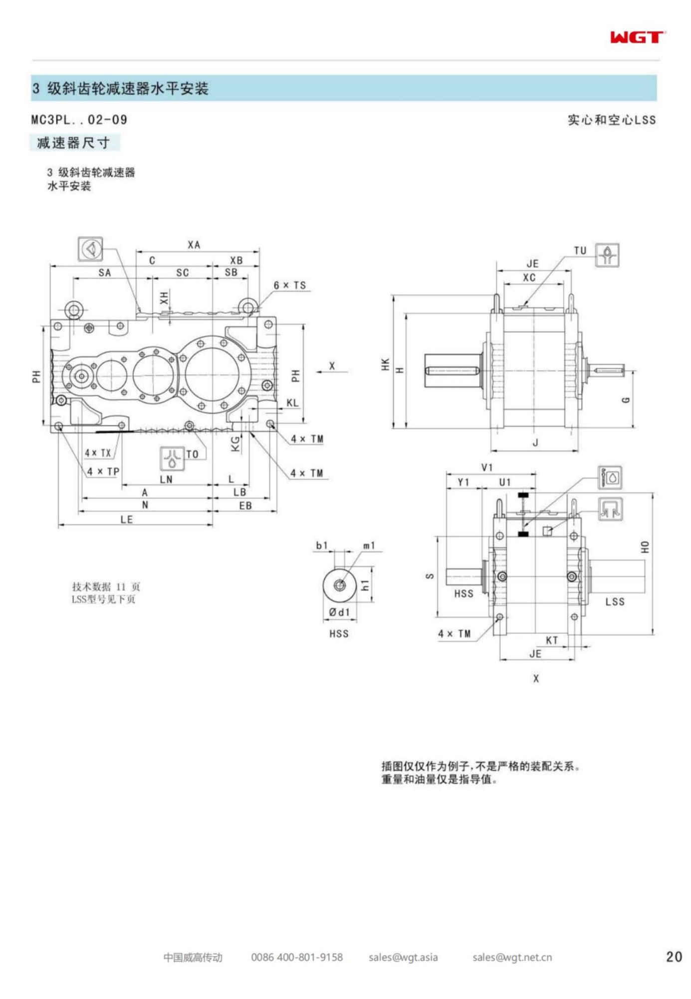
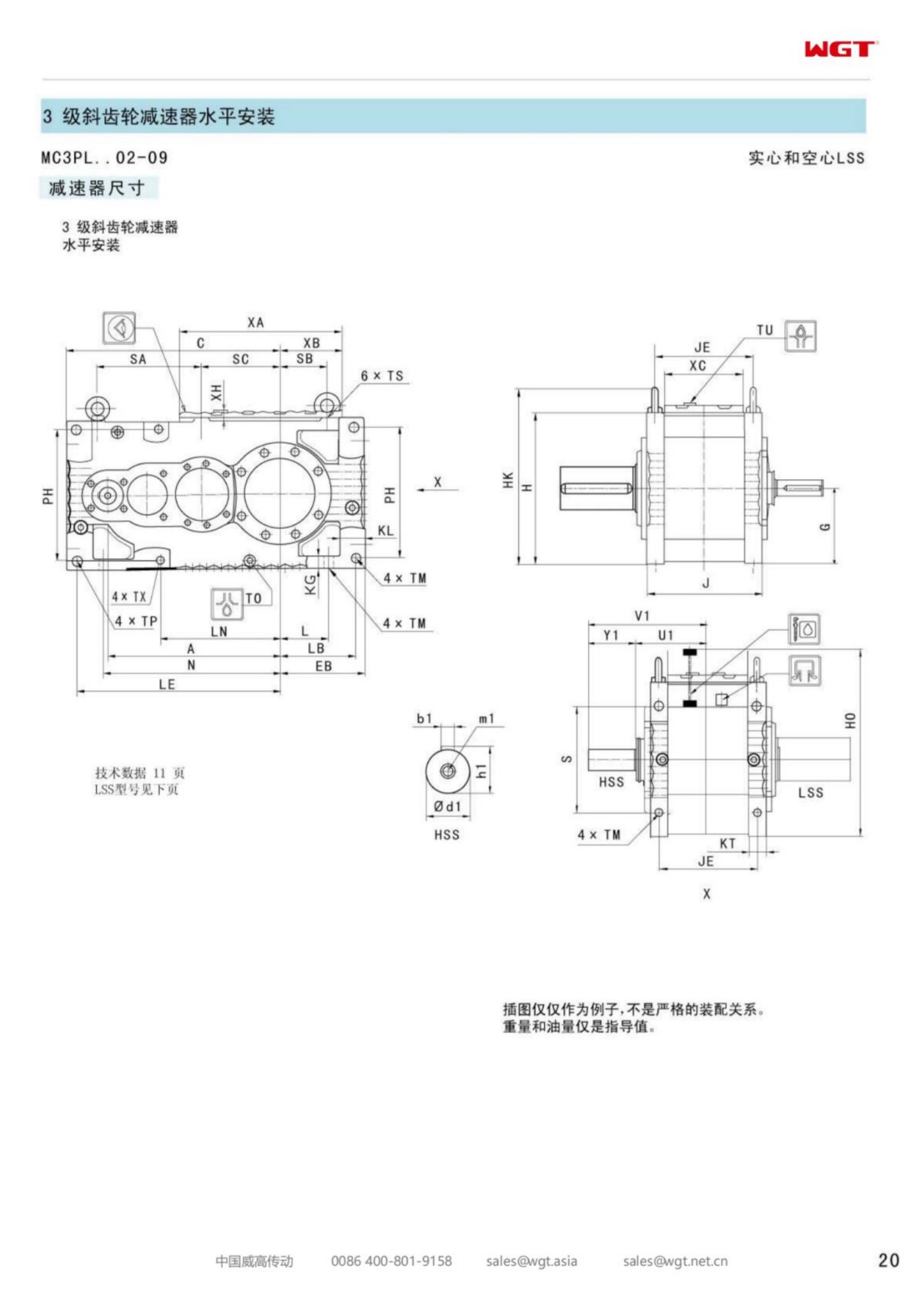
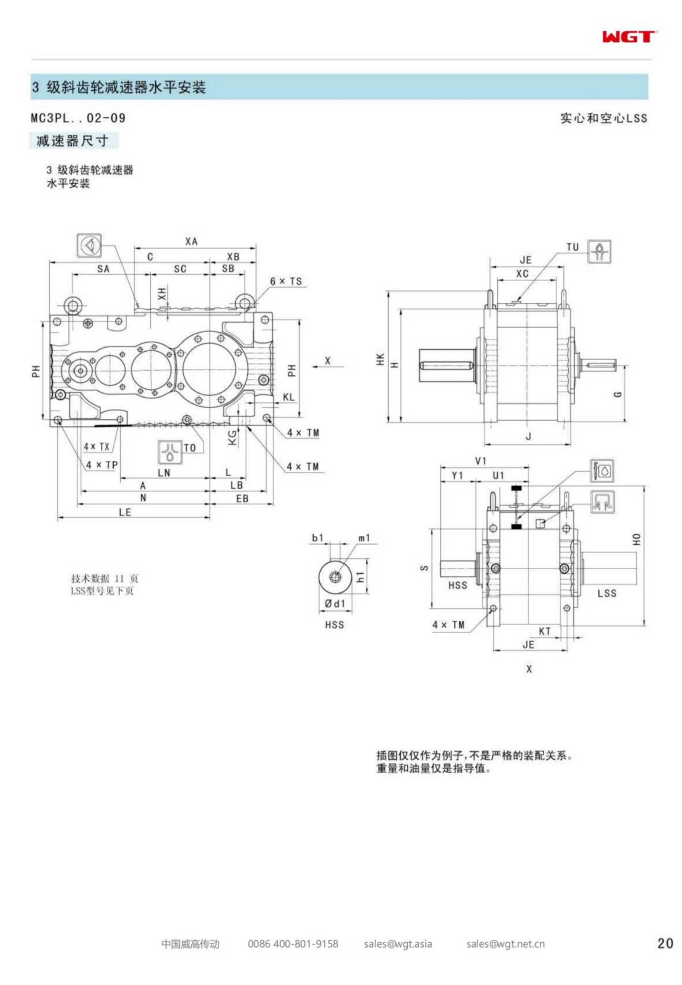
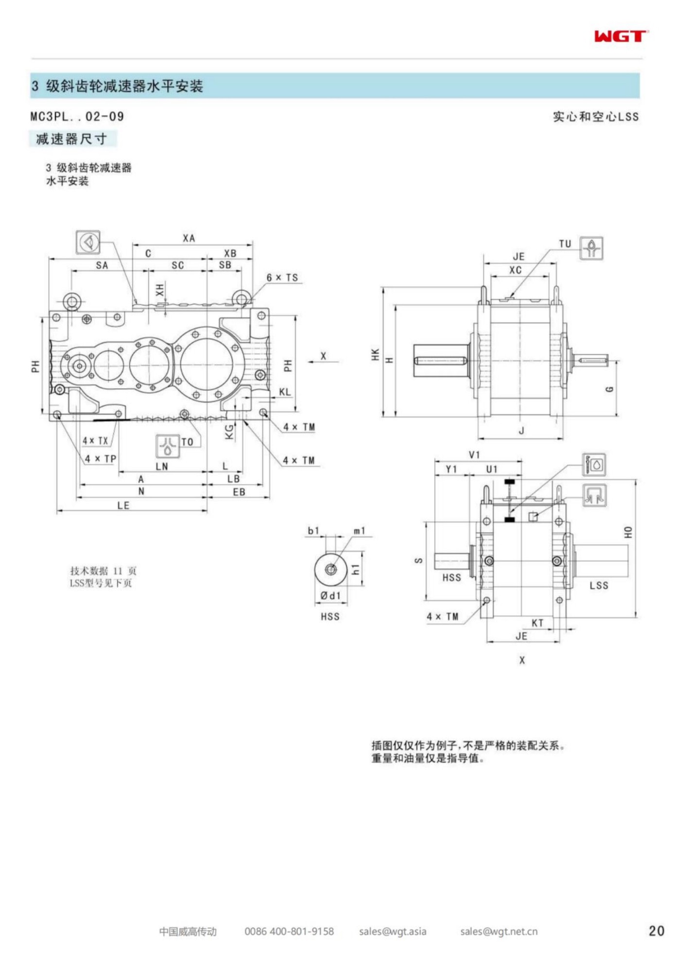
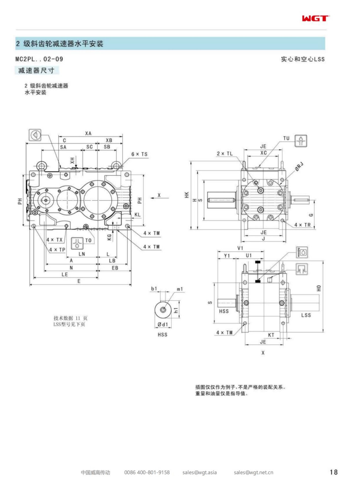
Most conveyors in a plant are pulled by their drive. A smaller, more awkward family is pushed by the load: the belt runs downhill, the loaded side descends, and gravity - not the motor - supplies the energy once the belt is up to speed. The MC2PLST06 solid shaft gearbox belongs to that world. It is the frame in the band where the questions change character: not how much torque the motor can deliver, but how much torque the load will deliver back, and what stands between that returned power and a conveyor running away down the incline.
Installers who treat a declining conveyor as an ordinary one usually find out during commissioning, when the drive is stopped and the belt creeps forward anyway. The gearcase itself is rarely the part that fails the test - it is the absence of a holdback, a brake sized for the wrong torque, or a coupling that was never asked to transmit power in the other direction. This page works through those decisions in the order they should be taken: the arithmetic of the incline, the device that stops runback, the sizing that respects overhauling load, and the details that keep the arrangement inspectable for the life of the conveyor.
Frame Six and the Arithmetic of Incline
Within this band, frame six is reached in two ways. A plant can arrive at it horizontally - a long, level trunk belt whose tonnage has grown until only the upper frames carry it - or it can arrive vertically, with a moderate tonnage lifted or lowered over enough height that gravity dominates the calculation. The second route is the one that produces the unusual enquiries, because a decline of a few degrees over several hundred metres can return more energy than the motor consumes, and the drive spends its working life as a generator whether or not anyone has designed for it.
The honest way to place the frame is to draw the load case twice: once with the belt starting, when inertia and friction both resist motion, and once running, when the descending load may be feeding power backwards through the gear train. Frame six has reserve for both pictures when they are written down. What it cannot do is infer them, and the two pictures are different enough that a selection made from a single kilowatt figure is a guess wearing a service factor.
Decoding MC2PLST06
The type string reads like the rest of the family with one new emphasis: the frame digit now sits at the point where regenerative duty usually lands.
| MC | Industrial gear unit family built for continuous plant duty |
| 2 | Two helical reductions in one level case |
| P | Parallel-shaft layout, input and output on parallel axes |
| L | Level build, both shafts horizontal |
| S | Solid output shaft, torque leaves through a coupling |
| T | Torque arm reaction, no feet, no foundation, no grout |
| 06 | Sixth frame: the step where declining and overhauling duties gather |
Read as an order document, the string fixes the geometry - parallel axes, horizontal build, solid shaft leaving through a coupling, reaction taken by an arm into structure. Everything that makes a declining conveyor safe lives downstream of that string: the holdback or the brake, the coupling that carries it, the service factor argued from the incline, and the control scheme for the start. A buyer who sends the string alone will get a well-made case and a site decision that was never really made.
When the Load Begins to Drive the Motor
On a declining belt the balance of power is a number, not an opinion. Friction resists motion and the descending load drives it; whichever is larger decides whether the motor is motoring or being driven. A shallow decline with a light load stays on the friction side. A longer decline, or the same decline carrying a heavier mineral, crosses the line, and from that moment every stop is a controlled event rather than a switch opening.
Three consequences follow, and they belong in the specification rather than in the commissioning engineer's notebook. First, the brake - if there is one - must be rated for the overhauling torque, which can be several times the motor's own contribution. Second, any device that prevents runback must hold from standstill, not merely slow the belt. Third, the gear train itself now carries torque from the output side, and every element between the belt and the motor - coupling, keys, shaft - should be checked in that direction too. None of this is exotic; it is simply a second direction of torque that the paperwork has to acknowledge.
Holdback or Brake: Choosing the Anti-Runback Device
The two classic answers to runback do different jobs, and large installations often want both. A holdback is a one-way clutch: it lets the drive turn in the lifting direction and locks instantly against reversal, with no control, no power and no setting to drift. A brake is a modulated device: it can hold, it can stop on a schedule, and it can be released for maintenance, but it depends on supply and on the integrity of its own mechanism.
The usual logic runs like this. If the worst case is a loaded belt creeping back the moment the motor stops - the classic inclined case - a holdback in the drive train settles it permanently. If the belt must also stop within a defined distance or time, or must be stopped deliberately for loading and trimming, a brake earns its place. Where the decline is steep and the belt is long, experienced operators specify the holdback for runback and the brake for stopping, and keep the two duties apart, because a single device asked to do both jobs is a compromise in each. Whichever combination is chosen, the mounting position - in the coupling on the output shaft, or on a dedicated extension - belongs on the same drawing as the bracket and the guard.
Sizing Against Overhauling Torque
The selection calculation for a declining conveyor has two rows, and the second one governs. The first row is the familiar one: running torque from the drive's own power, checked against the frame's rating with a service factor for the starts. The second row is the returned power case: the torque the load delivers downhill at continuous speed, and the peak it delivers when a fully loaded belt is stopped and held. The frame, the coupling and the holdback should each be checked against the larger of the two, and the larger one is not always obvious from the motor nameplate.
It is worth being explicit in the enquiry about which numbers were used, because a selection that looks generous on the motoring row can be marginal on the holding row. The figures that make the second row calculable are simple: incline, length, tonnage, belt speed and an estimate of friction. A supplier who receives them can return a selection with both load cases shown; a supplier who receives only a kilowatt figure can only hope the site remembered them.
What Belt Tension Asks of the Output Shaft
A decline changes the tension picture as well as the power picture. Where the load descends, the belt's tension is carried and balanced differently along its length, and the head shaft may see a pulled-together load rather than the pulled-apart load of an incline. For the gearcase, what matters is that the solid output shaft is specified for the torque of the holding case, with the key and the coupling hub sized for it, and that the reaction leaves through the arm into structure that has been checked for the same direction of load.
Two practical notes belong here. The torque arm sees its sharpest working on a holding event - the instant a loaded decline stops - so the arm's pins, bushings and the bracket welds deserve a place on the inspection list from the first year, not after a warning sign. And the coupling on a regenerative duty transmits torque in both directions, which makes its element condition and its hub fixing a shared item between the electrical and mechanical maintenance routines rather than one department's alone.
Coupling Details on a Regenerative Duty
When the same coupling must transmit motoring torque, holding torque and occasional reversal, its selection leans on the least glamorous of its qualities: fit, balance and the condition of its flexible element. Gear couplings and disc-pack couplings both appear on declining head stations; the choice usually follows the site's spares and the alignment the tower can actually hold. What the regenerative case adds is a demand for documentation - the element type, the torque rating, the tightening figures - because the coupling is now part of the safety argument, not merely the connection.
The guard deserves the same seriousness. A coupling on a decline duty does its most energetic work at the moment of a stop, and a guard that can be opened without tools tends to stay open. Bolted guards with a documented inspection window over the element cost little at order time and answer the question the site auditor asks first.
Duties That Belong on Frame Six
Conveyors running downhill under load, where power flows back and the holding case governs:
- Declining overland conveyor carrying ore down to a rail loadout at an iron ore mine
- Downhill clinker transport belt from the kiln line to the stockyard at a cement works
- Regenerative decline section of the coal handling plant at a power station
- Steep gallery conveyor at an underground salt mine
- Loaded decline conveyor from the quarry bench to the crusher station at a limestone operation
- Descending ship-feed conveyor at an aggregate export terminal
The common thread is elevation: tonnage that a smaller frame could carry on the flat becomes a frame-six duty once gravity joins one side of the ledger. In those positions the gearcase is the quiet centre of a small system - belt, shaft, coupling, holdback, brake, control - and the installations that run for decades are the ones where the system was ordered as one document.
Control of the Start on a Loaded Decline
Starting is the moment a declining conveyor is most alive. A fully loaded belt may begin to run the moment the holdback releases or the brake opens, and the drive has to gather it smoothly rather than be dragged to speed. Soft-start control, a variable-speed drive or a controlled coupling fill are all legitimate answers; the wrong answer is none of them, with the motor switched direct and the mechanical parts left to absorb the event.
The specification should say what the start must look like: acceleration time, the current ceiling the supply can accept, and whether the belt must be able to inch for maintenance. With those three lines written down, the control choice follows almost by itself, and the gearcase, the coupling and the holdback can be checked against a start that has actually been described instead of imagined.
Inspection Focus on a Drive That Coasts
A regenerative installation earns a slightly different inspection sheet. The items that matter most are the ones engaged only at the moments of transition: the holdback's internal condition at its scheduled internal check, the brake's pad wear and its achieved stopping distance, the arm pins and bushings, and the coupling element. Between transitions the drive behaves like any steady torque duty, and the ordinary disciplines - oil level and temperature, vibration at a fixed point, seal condition - apply unchanged.
One habit is worth building early: record the stopping distance of the loaded belt at commissioning, and repeat the measurement at each annual shutdown. A stopping distance that grows over the years is the earliest and cheapest warning that the brake, the holdback or the belt's condition has drifted, and it can be measured with a chalk mark and a stopwatch.
Commissioning Checks Specific to a Decline
The commissioning sequence for a declining conveyor adds three tests to the ordinary list. With the belt empty, run and stop normally, and confirm the brake and any control behave as specified. Then load the belt progressively and stop again at each stage, watching the stopping distance and listening to the holdback's engagement. Finally, prove the runback case deliberately: with the loaded belt stationary and the brake released under controlled conditions, confirm that the holdback locks and nothing moves. These are calm, methodical tests when they are planned, and they are emergency repairs when they are skipped.
The paperwork from those tests - the stopping distances, the currents at start, the temperatures after the first loaded hours - is the baseline the plant will compare against for years. On a duty where the load does the driving, that baseline is the closest thing the site has to a contract with the conveyor.
The Enquiry for a Regenerative Installation
A decline enquiry is a system document, and it is short if it is honest: profile and length of the decline, tonnage and belt speed, the motor and its control method, the required stopping behaviour, and the preferred arrangement for holdback and brake. A sketch of the head station with the available structural steel completes it. From that, the selection comes back with both load cases shown, a device list rather than a single gearcase, and the mounting drawings that let the tower be prepared before the equipment arrives.
The enquiries that produce trouble are the ones that describe only the motoring case, because the holding case will introduce itself on the first loaded stop. Frame six has carried declining and regenerative duties since the family's first years; what the frame needs from the buyer is simply the second row of the calculation, written down before the order instead of after the commissioning.
Questions We Hear Most Often
What happens if my duty changes after installation?
Send us the new duty point. A revised torque and service-factor calculation is free of charge, and the answer is usually one of three: the unit is fine, add an oil change interval, or plan a frame change at the next shutdown.
Can this unit mount on my existing installation without redesign?
Yes - the series is manufactured to the same centre distances, shafts and flange dimensions of the common industry frames, so couplings, guards and foundations stay untouched.
Which lubricating oil should be used?
GB L-CKC220~460 or Shell Omala 220~460 as supplied. Under normal duty the housing is lubricated for life; in hot or continuous-duty environments an oil change after the first 400 hours and then every 4000 hours is recommended.
Choosing the Right Frame Size
| Model | Centre distance | Output | Typical duty |
|---|
| M3PSF50 | size 50 | solid shaft, foot | conveyors, feeders |
| M3PSF60 | size 60 | solid shaft, foot | crushers, mixers |
| M3PSF70 | size 70 | solid shaft, foot | ball mills, shredders |
| M3PSF80 | size 80 | solid shaft, foot | kilns, heavy conveyors |
| M3PSF90 | size 90 | solid shaft, foot | mill and kiln drives |
| M3RSF50 | size 50 | solid shaft, foot, right-angle | inclined conveyors, elevators |
| M3RSF60 | size 60 | solid shaft, foot, right-angle | screw classifiers, feeders |
| M3RHF70 | size 70 | hollow shaft, foot, right-angle | agitators, drum drives |
| M3PHT80 | size 80 | hollow shaft, torque arm, parallel | shaft-mounted conveyors |
| M3RHT90 | size 90 | hollow shaft, torque arm, right-angle | heavy shaft-mounted drives |
One family, two layouts. Choose P for a coaxial-in / parallel-out drive train, R when the motor must turn 90 degrees; then pick the shaft type and mounting style that the machine interface needs.
Selection Example: Declining overland conveyor carrying ore down to a rail loadout at an iron ore mine
Take a 55 kW motor at 1485 rpm turning the head shaft at 31 rpm. The ratio follows directly: 1485 / 31 = 47.9, so a ratio near i=48 sits in the upper part of the two-stage band, and the frame is checked against the overhauling torque of the loaded decline as well as the motoring case, since the larger of the two governs every element from the belt to the holdback. In this case frame six carries the holding case with margin, the solid output shaft takes the holdback in the coupling, and the arm pins the reaction into tower steel that has been checked for a stop, not just a start. It always comes down to those three figures. Send them over and we confirm the frame, ratio and service factor in writing.
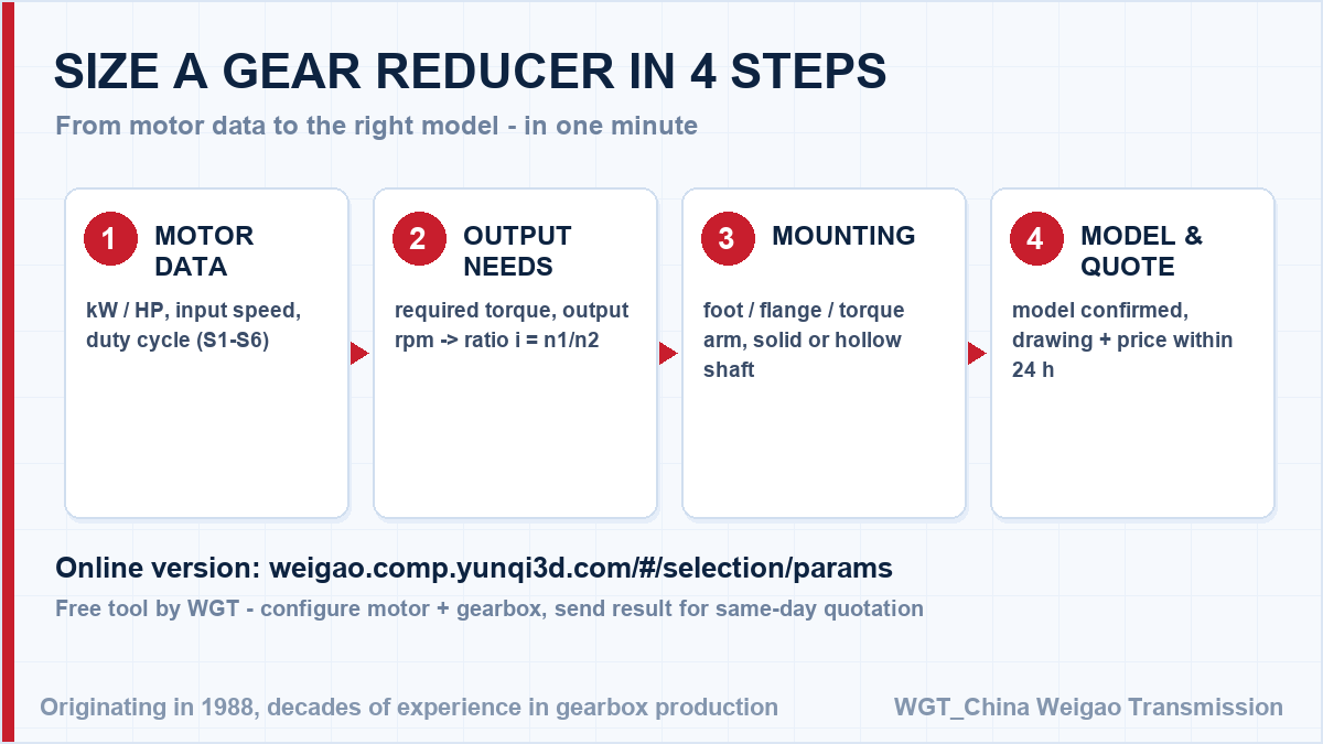
![online gearbox selection system workflow]()
Selection workflow used by our engineers for every quotation.
Real-World Duty Points
Stone quarry conveyor
A stone quarry runs reducers on its primary conveyor. Shock loads from oversized rock are absorbed by the case-hardened gears (surface HRC58-62), and after two years of continuous duty the units still run within their original 68 dB noise spec.
Flour mill screw conveyors
A flour mill standardised on gear reducers for its screw conveyor network. One spare-part pool now covers fifteen drives, and the smooth helical input stage keeps noise low in the packing hall.
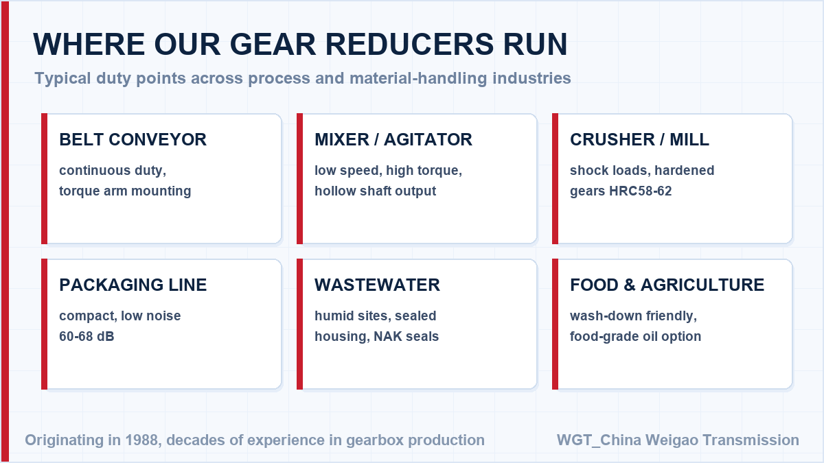
![right angle gearbox duty points overview]()
An overview of the duty points this series is built for.
OEM Framework Pricing and Reserved Capacity
Building machines in series? Use the WGT Motor & Gearbox Online Selection System to turn your motor data into a model number, and we will quote that exact unit within the day.
For OEM programmes we hold framework prices and reserve production slots for scheduled call-offs, so your line never waits on a gearbox. Ask for the framework terms with your first enquiry. Looking for a gearbox for mixer and agitator? Tell us the duty point and we will confirm the model in writing.