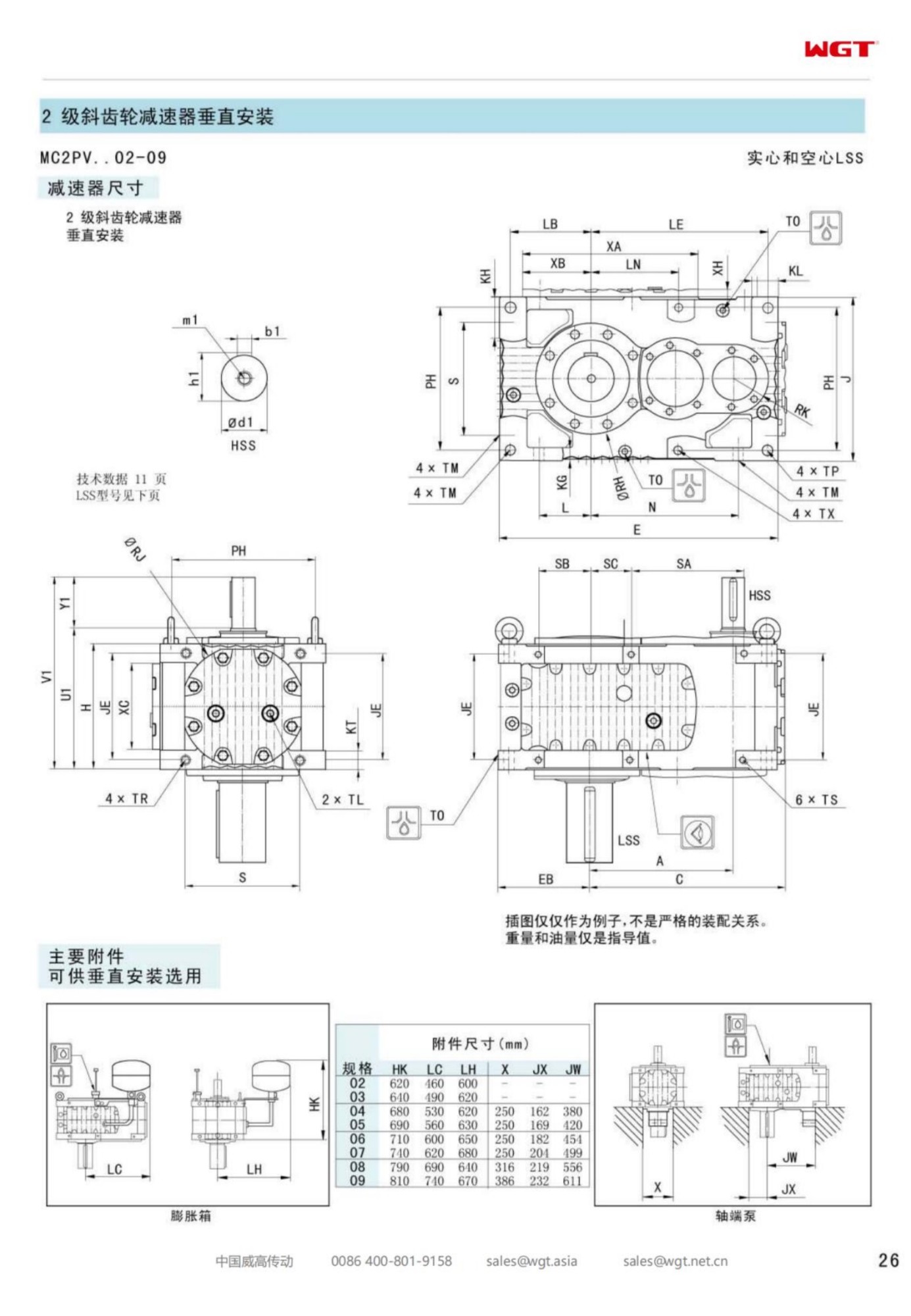
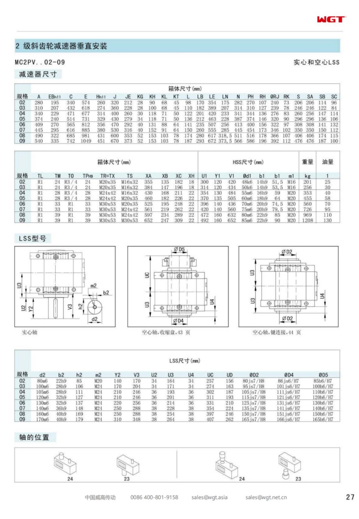
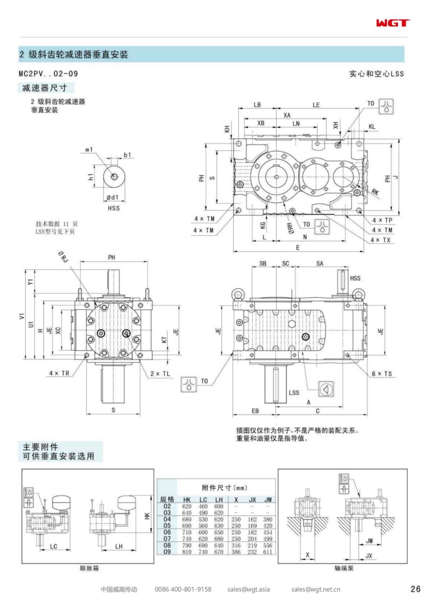
Most gearboxes sit beside the machine they turn, joined to it by a coupling, a bedplate and a set of alignment figures. The MC2PVHF02 vertical hollow shaft gearbox skips all three. Its output is a hollow bore, and the agitator shaft rising out of the vessel simply passes through it; the gearbox hangs on the shaft the process already owns, two helical stages turning inside a case that stands upright over the liquid. What looks like a small detail on the order sheet - H instead of S in the type string - redraws the whole mounting conversation.
Frame two is where most plants meet this construction for the first time. The duties are modest enough to forgive a first attempt, and the consequences of a wrong bore dimension or a skipped steady bearing show up early, in vibration and seal weeping rather than in wreckage. This page walks through the frame the way a fitter would: what the letters fix, how the load travels through a hanging case, what the oil and the seals need from a vertical position, and how the unit goes on - and comes off - without disturbing the vessel.
The Gearbox That Hangs on the Process Shaft
Every coupled drive line carries an alignment responsibility: motor to gearbox, gearbox to load, each interface measured and shimmed and re-checked after the first thermal cycle. A hollow-bore vertical drive deletes the second interface entirely. The gearbox grips the agitator shaft directly, so the only alignment that matters is the one the vessel builder already delivered - the shaft's verticality and its runout at the drive position. The plant does not commission a coupling; it commissions a fit.
The deletion cuts both ways, and honest buyers note both. What the plant gains in simplicity it gives up in separation: there is no coupling element to sacrifice first, no spacer to remove for seal service, no flex point to absorb the shocks the process delivers. The gearcase itself becomes the flexible member, which is why the bore fit, the key and the shaft's surface finish deserve the attention a coupling would otherwise have received. A drive that hangs on the shaft is only as good as the fit that hangs it.
Decoding MC2PVHF02
The type string fixes the geometry a vertical buyer cares about, letter by letter.
| MC | Industrial gear unit family built for continuous plant duty |
| 2 | Two helical reductions inside one upright case |
| P | Parallel-shaft layout, input and output on parallel axes |
| V | Vertical build, output axis pointing down into the vessel |
| H | Hollow output bore, the process shaft passes through it |
| F | Footed reaction pads, bolted to the vessel bridge or plate |
| 02 | Second frame, the entry tier of the vertical hollow band |
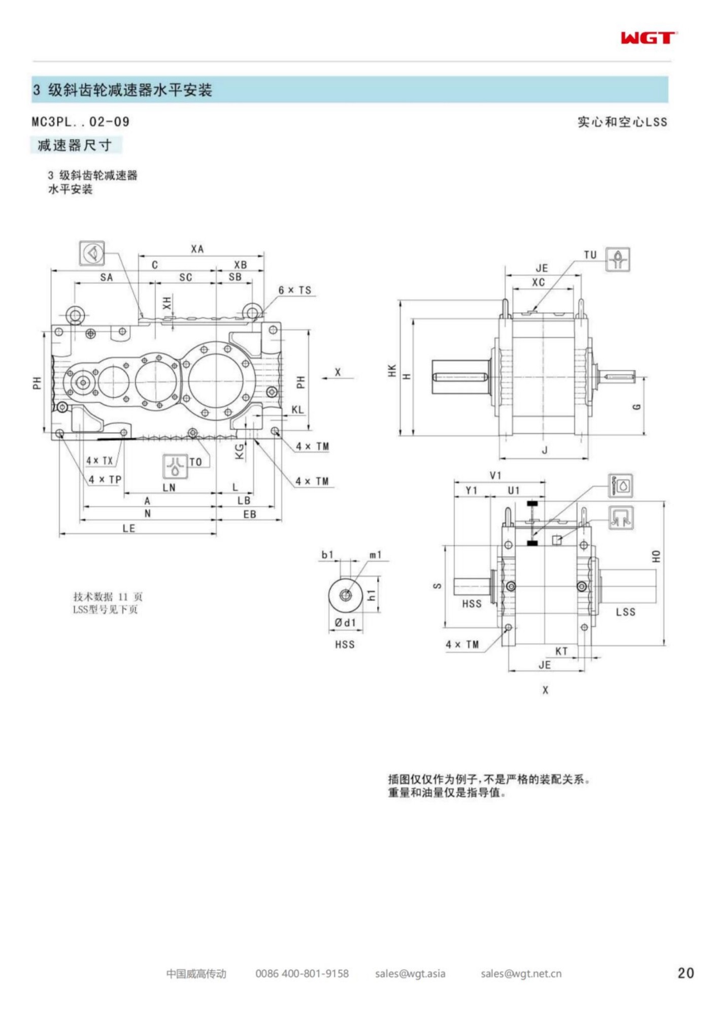
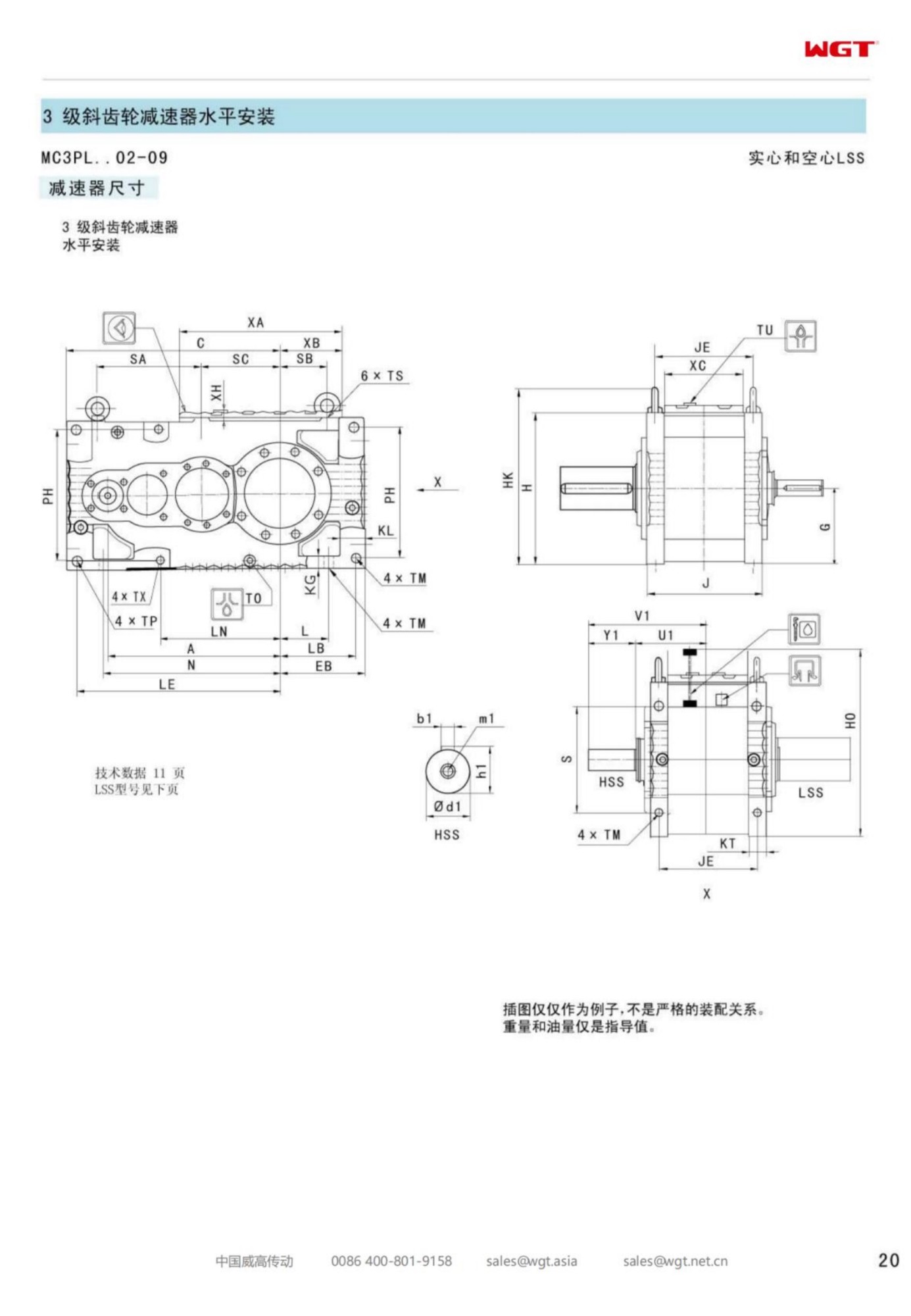
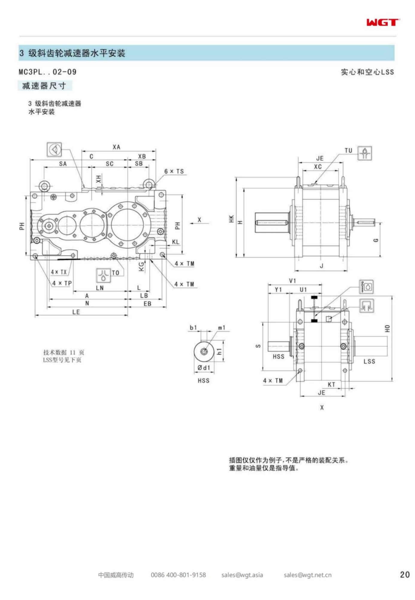
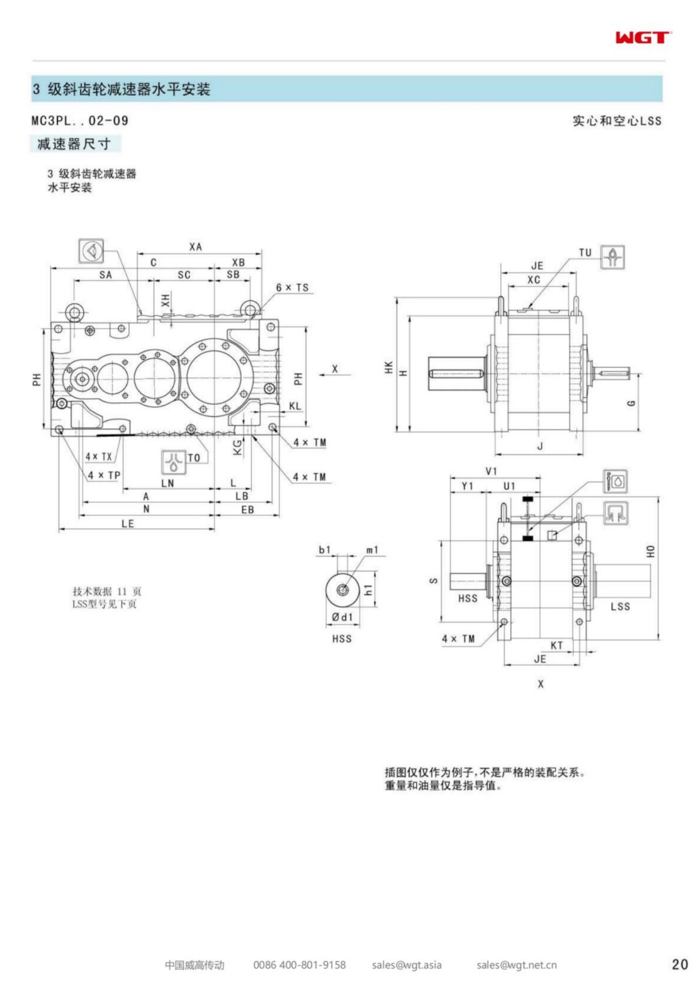
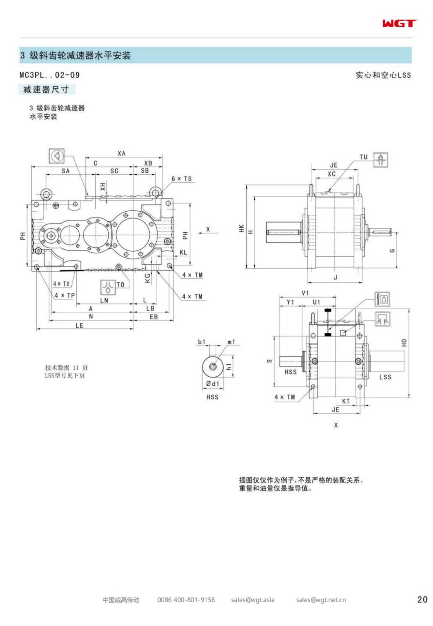
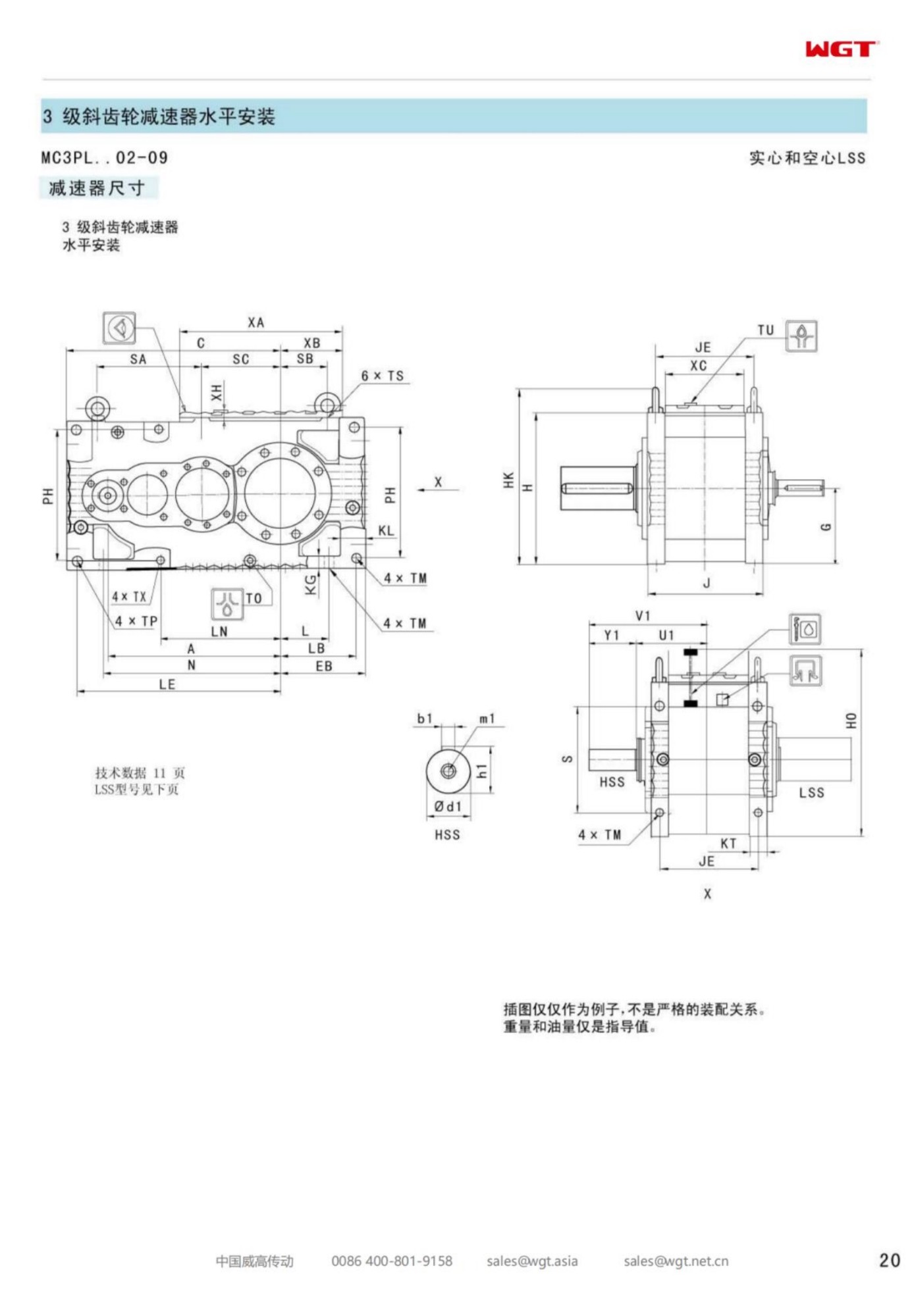
Read as an order document, the string tells the factory what to build and tells the site what to prepare: a bridge that can carry the hanging weight, a shaft whose diameter and key match the bore drawing, and headroom above the vessel for the unit to be lifted on and off. What the string cannot fix is the fit quality at the bore - and on a hanging drive, that fit is the whole installation.
Two Stages Above the Liquid
The two-stage arrangement is the quiet reason this frame suits vessel duty. Agitator speeds sit far below motor speed, and the two helical reductions deliver the deep ratio without the sliding contact a worm stage would bring. Efficiency stays high through long loaded hours, which matters in a hall where a dozen drives run continuously and every wasted kilowatt heats both the oil and the room.
The helical stages also run quietly enough that the drive's health can be judged by ear from the vessel top - a feature operators use more than any instrument. When the character of the noise changes with product level or viscosity, the hall hears it in a week. That early warning is worth as much as the efficiency number, because a vertical drive over a full vessel is not a drive anyone wants to open on a hunch.
The Bore, the Key and the Steady Bearing
Three components share the mechanical work in a hanging drive. The bore carries the torque through its fit and its key, the keyway edges delivering every start and viscosity spike the process can stage. The reaction pads on the gearbox feet carry the torque reaction back into the bridge. And the steady bearing at the bottom of the shaft - if the vessel has one - carries the lateral load the long shaft would otherwise hand to the gearbox bearings.
The failures this frame sees are almost always one of the three, not the gears. A keyway that has brinelled from loose starts, pads shimmed instead of seated, a steady bearing worn quietly for years - each announces itself as vibration that gets blamed on the product or the impeller. The inspection routine is therefore short and pointed: key and keyway at every lift-off, pad seating annually, steady bearing on the same calendar as the seals.
Load Paths on a Hanging Drive
Gravity pulls the gearbox's full weight down the shaft and into the vessel's internal structure; the process pushes bending and thrust back up; the torque reaction twists the bridge through the feet. A coupled drive spreads these loads across a bedplate and a foundation. A hanging drive concentrates them at two interfaces - the bore and the bolted pads - and the structure around those interfaces decides whether the drive runs quietly for twenty years or walks itself loose in three.
The practical consequence belongs in the enquiry: the vessel bridge must be checked for the hanging weight plus the torque reaction, not just the weight. Structural engineers who receive the drive's mass, the reaction figure and the bolt pattern can answer in a page. Buyers who omit the numbers buy a site argument instead, usually discovered when the crane arrives and the bridge drawing says nothing about torsion.
Duties That Suit the Second Vertical Frame
Hollow-bore vertical drives that hang straight on the process shaft - no coupling, no alignment day:
- Agitator drive on a fermentation vessel at a biotech plant
- Flash mixer basin in a municipal water treatment train
- Cooker shaft on a starch slurry line in a food plant
- Dye-vat circulation drive in a textile works
- Rake mechanism inside a circular clarifier
- Paddle mixer over a pigment holding tank in a paint plant
What these duties share is a shaft that already exists and a roof that is already busy. The hollow-bore frame borrows the first and stays out of the second, which is why plants standardise on it once the first installation has run through a cleaning cycle without a single coupling complaint.
Keeping Oil at the Gears While the Case Stands Up
An upright case embarrasses ordinary lubrication. The oil sits against the output seal, the upper bearings lose their splash, and every thermal cycle breathes the case in and out through its lowest point. This build answers with internal baffling and a lubrication arrangement designed for the vertical position from the start - but the design only works when the correct grade goes in and the level is checked from the marks the vertical position actually provides, not the habits of a horizontal frame.
The operating discipline is correspondingly simple: the first oil change at the interval the book states for a new upright case, then samples on a schedule long enough to show a trend. Water in the oil is the finding to watch in a washdown hall; it arrives through the breather or a tired seal and shows in the sample months before it shows in the bearing. Plants that sample quarterly on this frame catch the entry path while it is still a part number instead of a teardown.
Sealing a Hanging Case Against Vapour and Washdown
The output seal on a vertical unit works in the worst seat in the house: below the oil level, above the process, and directly in the path of whatever the vessel breathes out. Vapour, humidity and cleaning water all queue at that lip. The standard seal handles most duties; fermented broths, hot caustic washdowns and outdoor tanks justify the upgraded lip material or a lipped sleeve that throws water clear before it reaches the seal.
Above the oil, the breather decides how much of the hall's atmosphere the case inhales. A filtered breather suited to the duty - washdown type in wet halls, desiccant outdoors - turns the daily thermal cycle from an ingestion pump into simple breathing. Neither part is expensive, and both are chosen at order time; retrofitted onto a drive hanging over a full vessel, they cost a shutdown apiece.
Fitting the Frame and Lifting It Off Again
The installation sequence rewards preparation. Shaft runout and diameter are recorded before anything travels to the vessel; the bore and key are tried dry at ground level; the bridge bolts are checked for thread engagement and pad seating before the crane is booked. On the day, the unit slides down the shaft, the key seats, the pads pull down onto their shims, and the whole operation is measured in hours - not days, because there is no coupling to align and no bedplate to grout.
Removal is the same film reversed, with one addition: the lift-off is the best inspection the drive ever gets. Key and keyway, bore surface, seal lip and pad seating are all exposed at once, and every finding is written against the drive's record. Plants that treat each lift-off as an inspection build the baseline that later decisions stand on; plants that treat it as a interruption skip the notes and relearn the shaft's history the hard way.
Bore Dimensions and the Shaft That Must Match
The bore is ordered to a shaft, not to a catalogue habit, and the shaft that arrives on site sometimes differs from the drawing that left the office - turned down after a repair, built to an older standard, or simply measured wrong. The discipline is mechanical and unchanging: measure the actual shaft at the drive position, in three planes, with the surface finish noted, and send those numbers with the order. The factory bores to what it is told; it cannot bore to what the vessel was supposed to have.
Where a fleet of vessels carries several shaft diameters, the frame's adapter options earn their keep: sleeve kits that let one spare gearbox serve several shafts, and bore reduction sleeves that fit a new drive to an old shaft without machining the shaft itself. A buyer who states the fleet's diameters at order time receives options instead of surprises - and keeps one spare instead of three.
Watching the Drive From the Vessel Top
A hanging vertical drive is inspected from above, and the inspection is short because the drive is exposed: oil level through the sight glass, temperature by hand on the case, noise against last month's memory, bolt torque on the pads annually, seal lip watched for the first weep. Fifteen minutes a month per drive, taken while the operator is already on the platform for other reasons, is the entire monitoring programme most of these frames need.
The trick is keeping the readings comparable. A note in the log with a date, a level and a temperature takes a minute and turns next year's 'has it always run this warm' into a factual answer. Vertical drives over live vessels punish curiosity expensively; the log is the cheapest form of curiosity the plant can buy.
The Enquiry That Keeps the Bore Honest
The enquiry for this frame is the standard duty sheet plus four vertical lines: the measured shaft diameter and key at the drive position, the hanging weight and torque reaction the bridge has been checked for, the seal and breather package the atmosphere demands, and the lifting access above the vessel. Suppliers answer sheets like this with firm figures, because nothing in them requires a site visit to guess.
The drives that disappoint are rarely undersized; they are mis-fitted. A bore ordered from a drawing instead of a measurement, a bridge approved for weight but not reaction, a breather chosen for price instead of atmosphere - each is an omission the order could have caught. Frame two forgives most of these once. The fleet that follows it does not, which is why the first enquiry is worth writing carefully.
Selection Example: Agitator on a fermentation vessel at a biotech plant
Take a 15 kW motor at 1465 rpm turning the agitator shaft at 37 rpm. The ratio follows directly: 1465 / 37 = 39.6, so a ratio near i=40 comes out of the two-stage band, and the hollow bore is specified to the measured agitator shaft so the unit hangs on the shaft without a coupling to align. In this case frame two carries the duty with the bore doing the alignment work, and the steady bearing at the vessel floor takes the lateral load the long shaft would otherwise hand to the gearbox bearings. That is the whole calculation. If your duty involves heavy starting, frequent reversing or many stops per hour, tell us and we raise the service factor.
Which Frame Size Do You Need?
| Model | Centre distance | Output | Typical duty |
|---|
| M3PSF50 | size 50 | solid shaft, foot | conveyors, feeders |
| M3PSF60 | size 60 | solid shaft, foot | crushers, mixers |
| M3PSF70 | size 70 | solid shaft, foot | ball mills, shredders |
| M3PSF80 | size 80 | solid shaft, foot | kilns, heavy conveyors |
| M3PSF90 | size 90 | solid shaft, foot | mill and kiln drives |
| M3RSF50 | size 50 | solid shaft, foot, right-angle | inclined conveyors, elevators |
| M3RSF60 | size 60 | solid shaft, foot, right-angle | screw classifiers, feeders |
| M3RHF70 | size 70 | hollow shaft, foot, right-angle | agitators, drum drives |
| M3PHT80 | size 80 | hollow shaft, torque arm, parallel | shaft-mounted conveyors |
| M3RHT90 | size 90 | hollow shaft, torque arm, right-angle | heavy shaft-mounted drives |
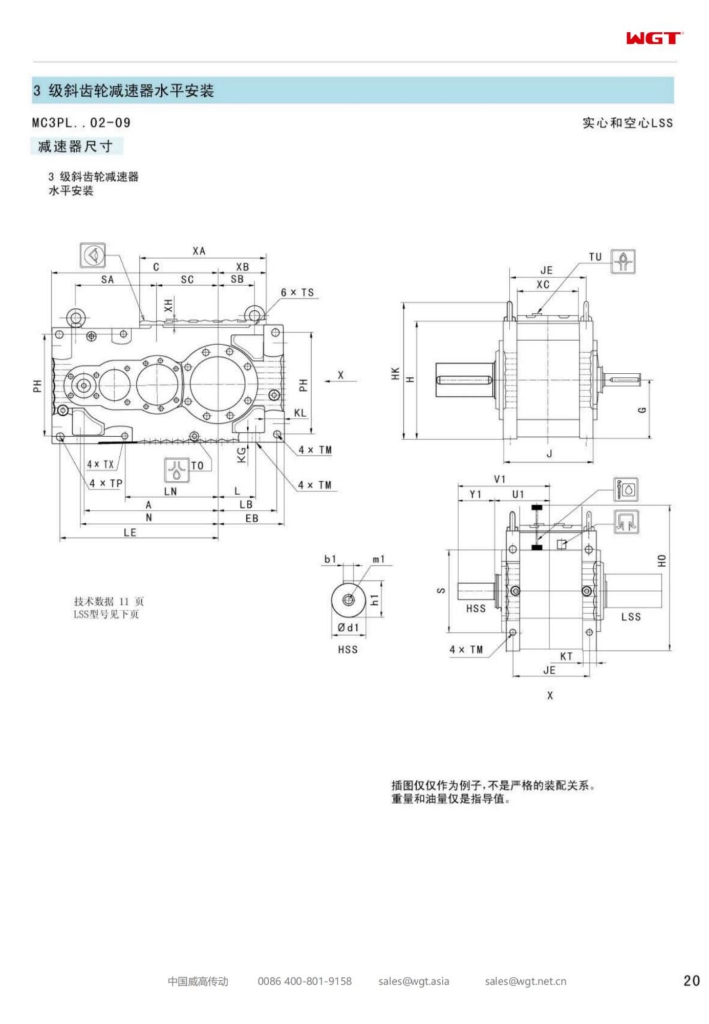
Foot-mounted frames are listed below; torque-arm (T), hollow-shaft (H) and vertical (V) variants are available across the size range. Ask for the outline drawing to check the interface before ordering.
Answers to Common Questions
How do I install the unit on an inclined conveyor?
Mount the unit with the output shaft horizontal or as recommended for your mounting position, and choose the anti-run-back option so the loaded belt cannot drive the gearbox backwards when power is cut. Tell us the incline angle when you order.
What is the difference between a keyed hollow shaft and a shrink-disc connection?
A keyed hollow shaft is the economical choice for normal torque and easy maintenance. A shrink-disc connection transmits higher torque with zero backlash and no keyway wear, and is preferred for reversing or high-torque duties.
Can I get a CAD drawing or 3D model for my design review?
Yes. Send us the model and ratio and we provide a 2D dimension drawing and a 3D STEP model for your review, usually the same working day. Drawings follow the layout of the original series so they drop into your existing assembly.
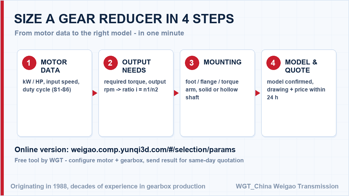
![gearbox sizing steps for engineers]()
Four steps from your application data to a firm model number.
Case Notes from the Field
Cement plant clinker belt
A cement plant drives its clinker transport belt with reducers in dusty, high-ambient conditions. Sealed housings and a 40 deg C maximum temperature rise let the units sit close to the kiln without extra cooling.
Paper mill pulp agitator
A paper mill uses reducers on pulp chest agitators. Continuous 24-hour duty is handled by lifetime lubrication, and the low backlash keeps the agitator steady when the stock consistency changes.
![industrial gear unit application overview]()
A cross-section of the installations we supply every month.
Drive Down? Ask About Priority Builds
A drive is down right now? Try the WGT Motor & Gearbox Online Selection System, then send the result sheet - we return a complete datasheet, drawing and price the same day.
Priority builds slot into the next production run, and urgent units can be air-freighted within days of payment. Describe the failure and the machine - we tell you honestly what is possible. Looking for a gearbox for crusher? Tell us the duty point and we will confirm the model in writing.