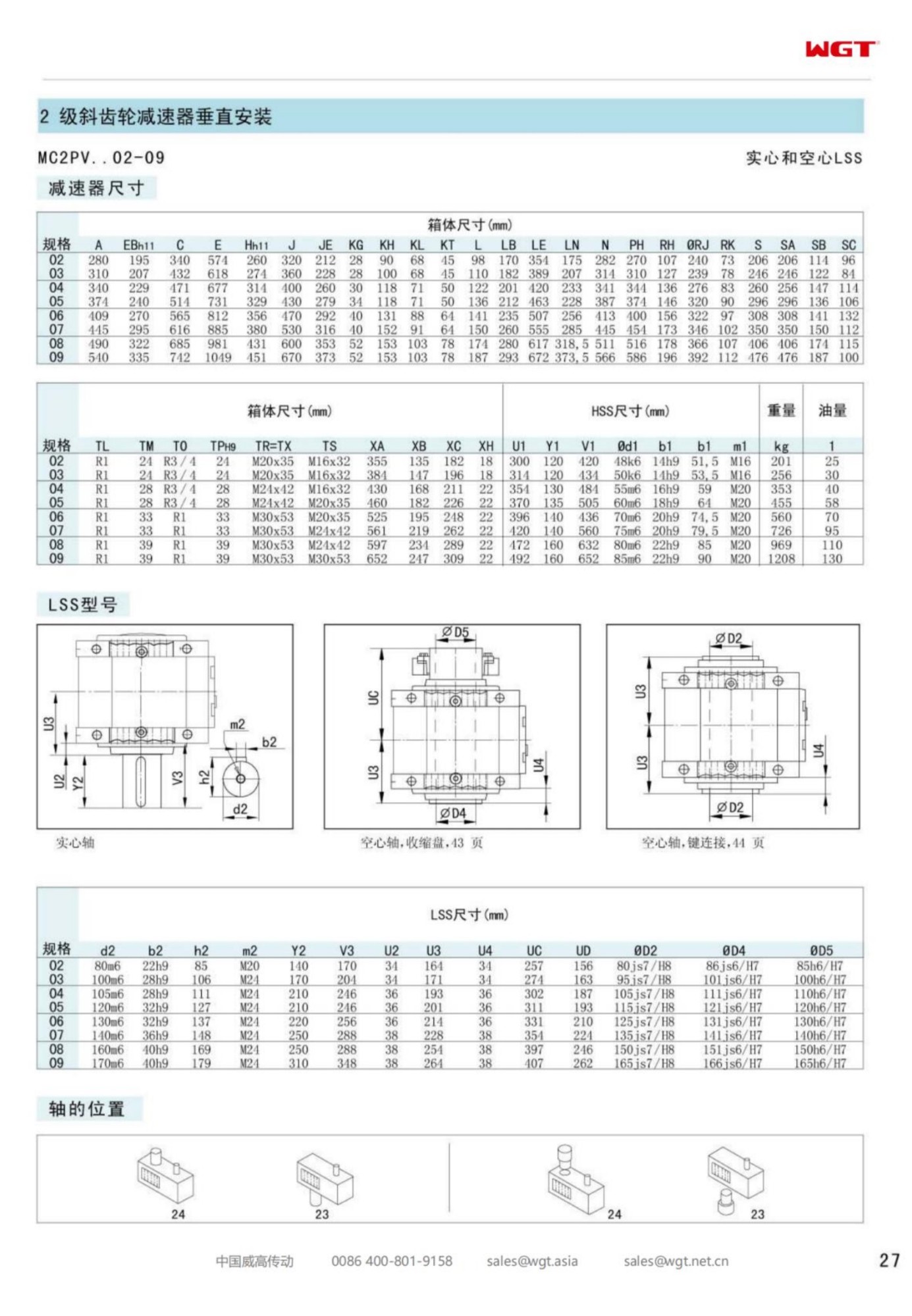
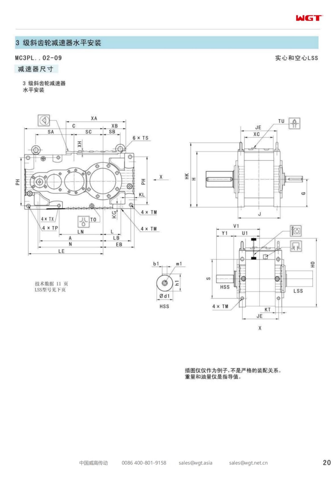
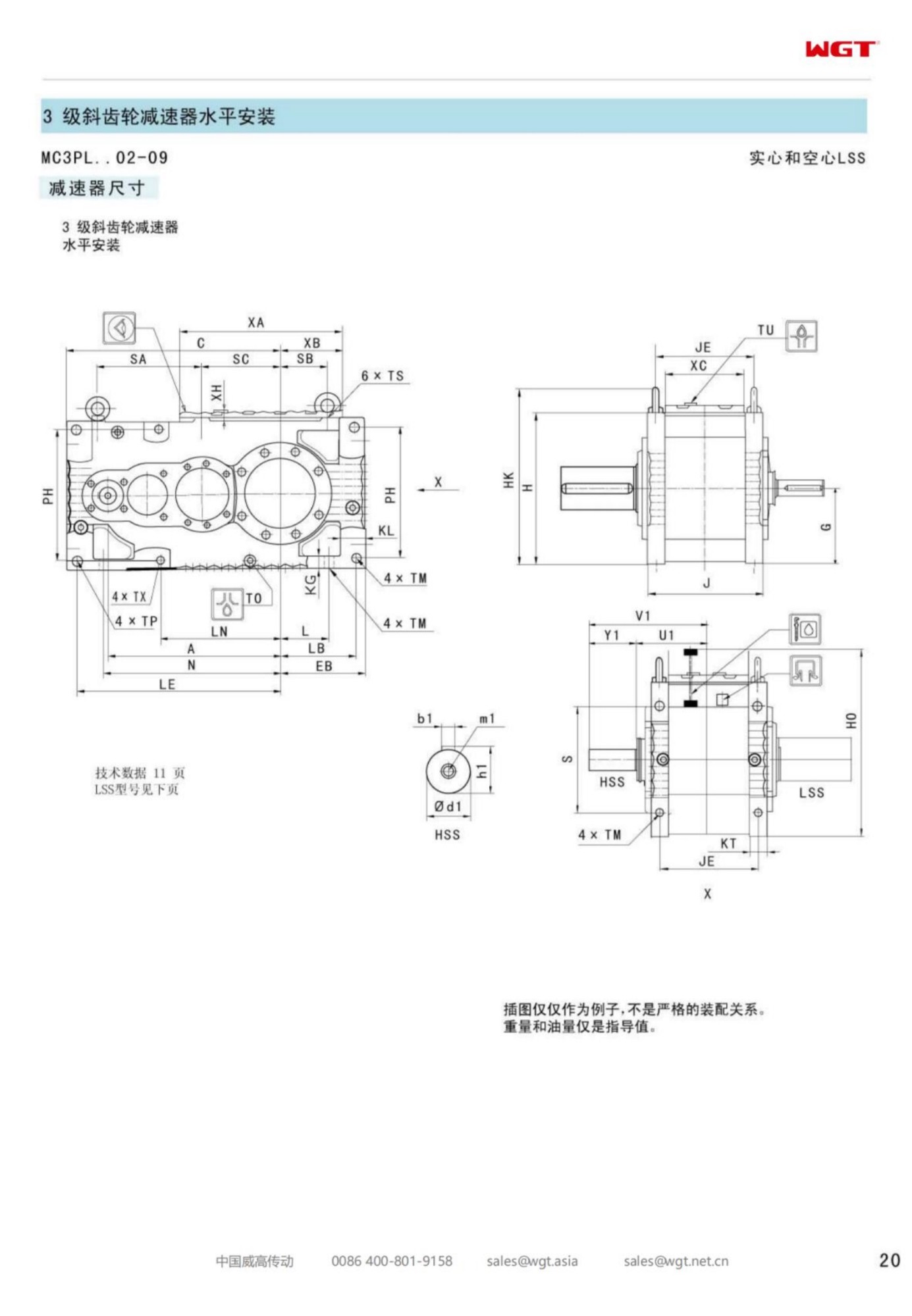
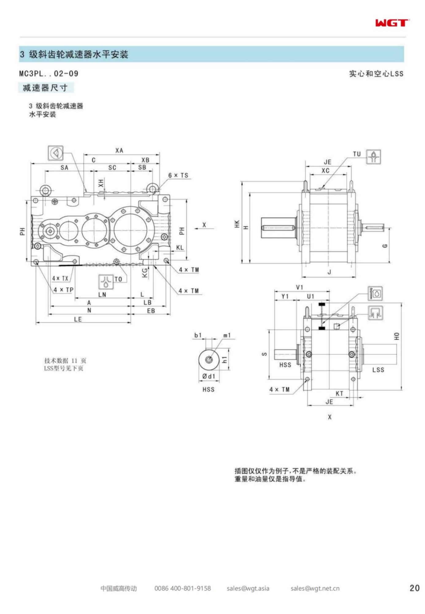
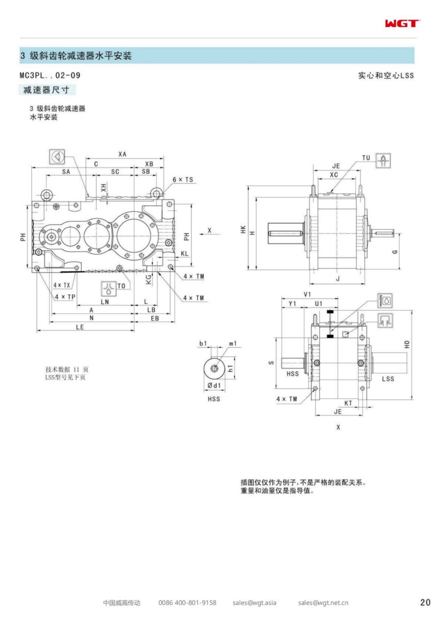
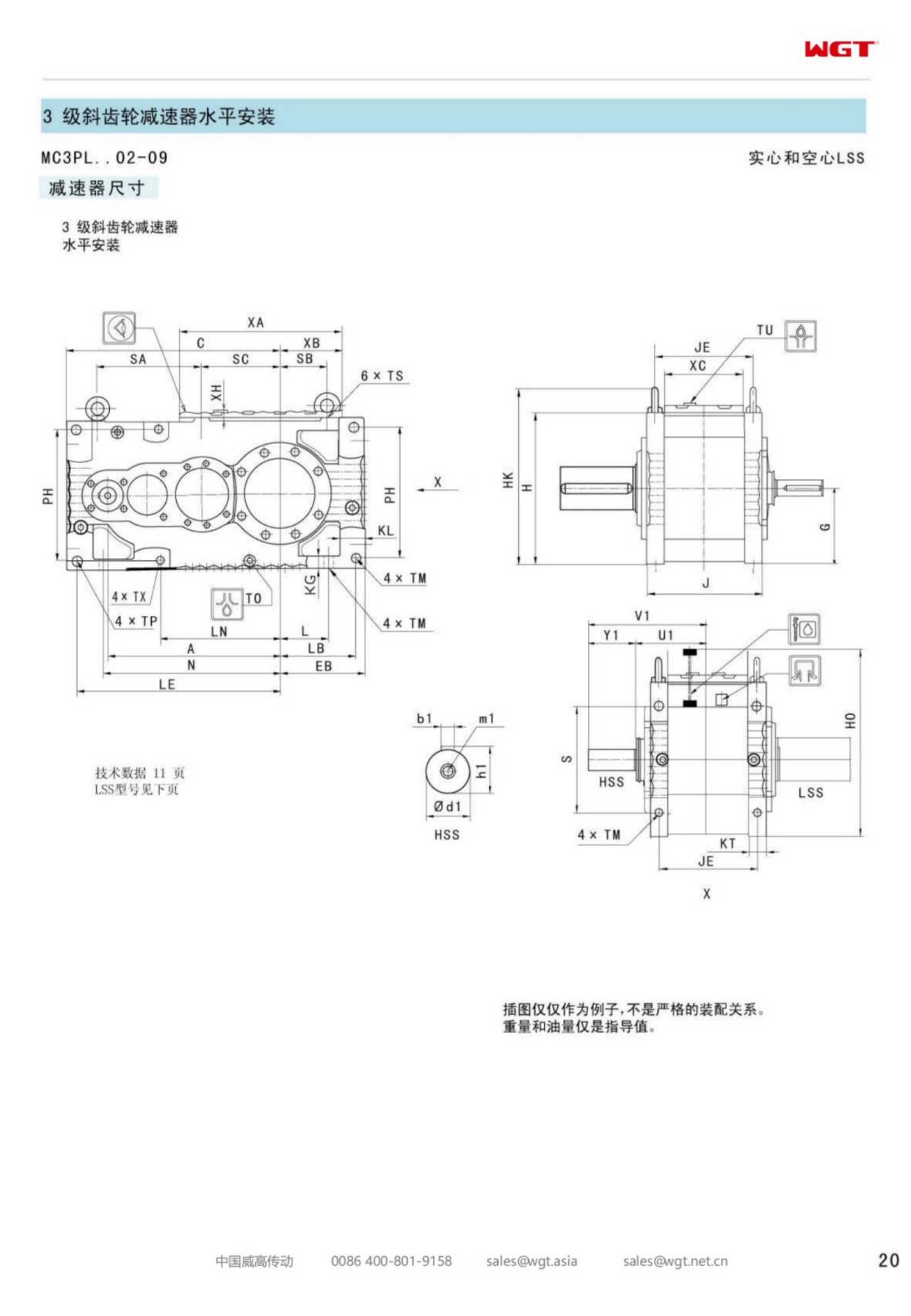
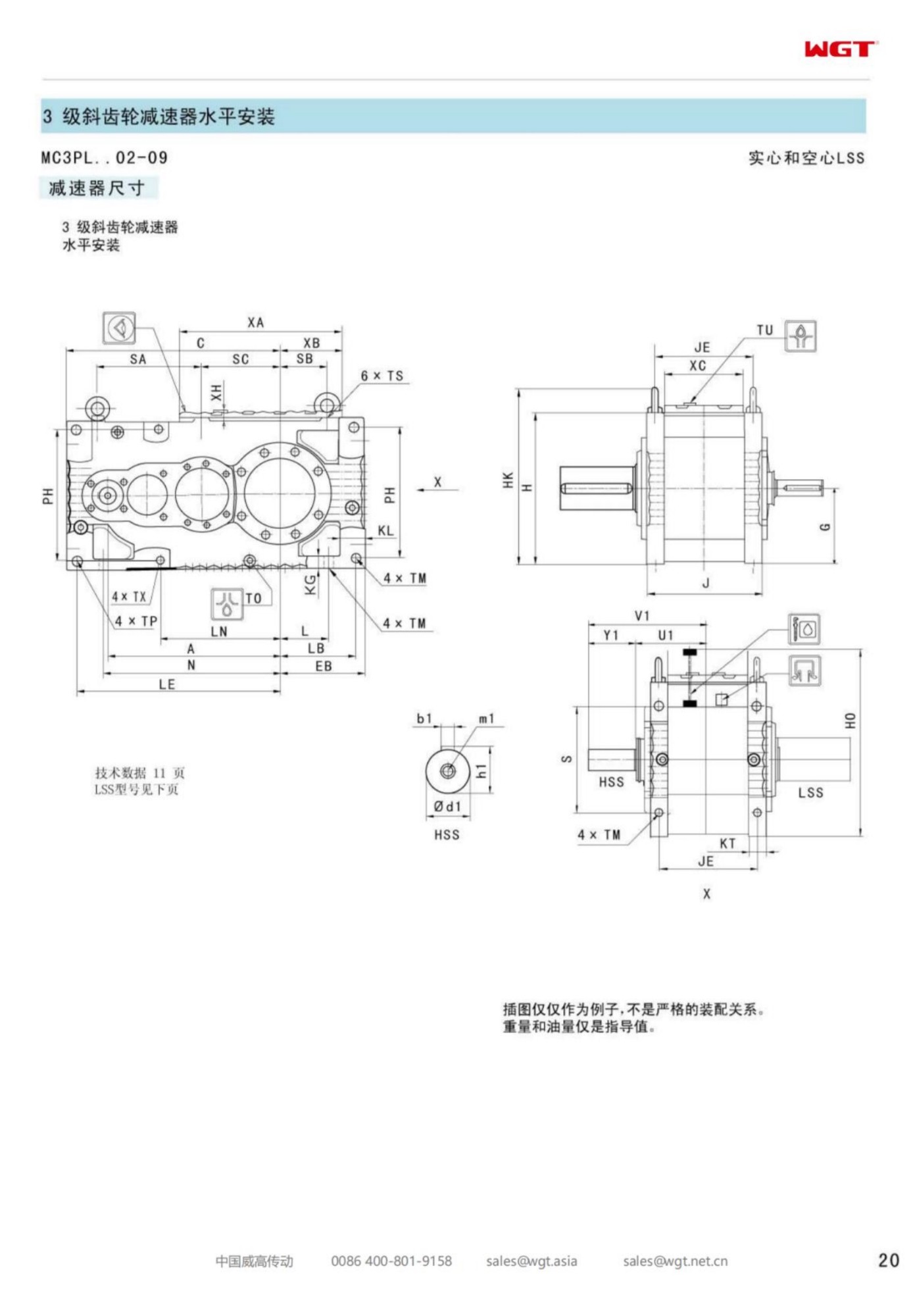
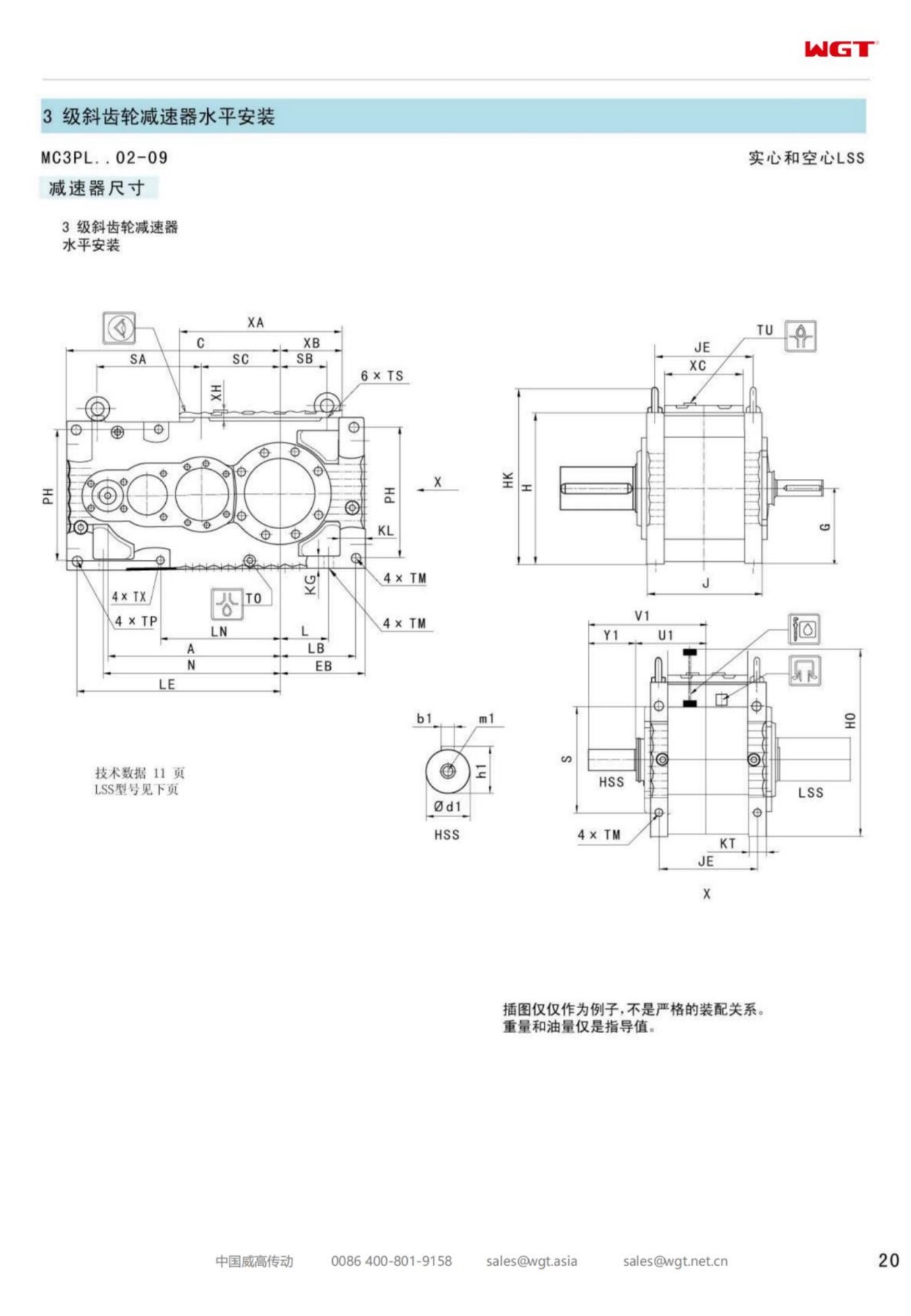
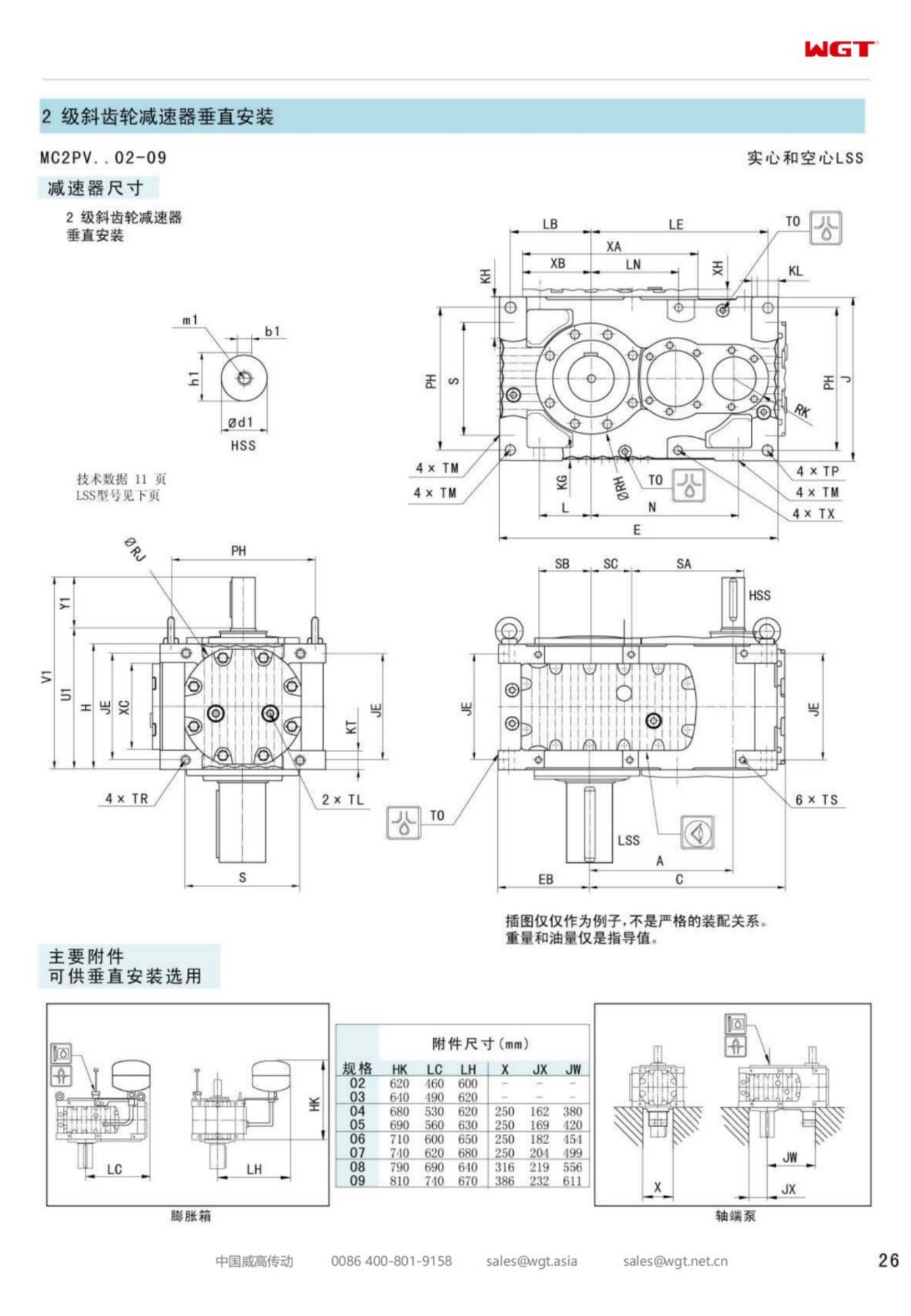
Near the top of any vertical line the buyer's questions change character. Below the fifth frame they are about capacity and ratio; at the seventh they are about who carries which risk. The MC2PVSF07 vertical gear unit is the widest of the standard-foot mounted verticals in this family: two helical stages in one plane, a case built to sit on a bridge plate, and a solid coupled shaft delivering torque straight down into the process. It exists for the plants whose tanks are large enough that the drive is one line on a structural drawing among many.
This page is organised the way those plants buy - not around the gear geometry, which is settled, but around the four decisions that actually determine whether the installation runs for thirty years: who takes the thrust, who designs the plate, who owns the shaft, and who signs off the start.
The Seventh Frame in Plain Terms
Interpreted strictly, the designation tells you everything you need before opening a catalogue.
| MC | Industrial multi-stage gear unit family |
| C2 | Compact two-stage parallel-shaft series |
| P | Parallel stages - input and output shafts in one plane |
| V | Vertical build, output facing downward |
| S | Solid output shaft, connected through a coupling |
| F | Foot mounting to a bridge or top plate |
| 07 | Seventh frame - widest standard foot-mounted vertical here |
The value of reading it this way is diagnostic. If a site reports a drive that will not hold alignment, the letters say where to look: a V build points at plate level and case squareness before anything internal; an S build points at the coupling and the driven element's own bearing. Half of all field complaints about vertical drives are settled by reading the designation and then looking at the plate.
Thrust: The First Question Nobody Asks
On a vertical installation the axial load from the driven element has to land somewhere, and there are only two honest answers: the gearbox carries it, or the driven machine carries it in its own bearing. Both arrangements exist and both work; what does not work is leaving the question unanswered until the first shutdown.
Where the gearbox carries the thrust, the output bearing is selected for it and the coupling is a simple torsion path. Where the driven machine carries it, the shaft ends in a coupling that transmits torque only and the gearbox is relieved of an axial duty it was never asked to survive. The engineer who specifies the vessel should state the choice in the enquiry, because the two arrangements produce different drawings and different spare parts lists. A supplier guessing at this is a supplier who has decided to bill the difference as a change order.
Who Designs the Plate Under the Feet
At frame seven the mounting plate is a piece of structural engineering, and the division of responsibility should be written down before the order. The usual clean split: the gearbox supplier provides the bolt pattern, the reaction torque and the unit mass with its centre of gravity; the fabricator designs the plate, gussets and bracing to those figures and checks the structure's natural frequency against the driven element's pass rate.
Two habits make that split work. First, get the reaction torque figure at quotation, not at delivery - fabricators order steel on the quotation drawing. Second, ask for the bracing check in writing, even when the answer is one line. A bridge that resonates at the paddle frequency will transmit its complaint into the gearbox bearings, and the warranty conversation that follows is never about the bridge.
Duties That Choose the Widest Vertical
The widest standard vertical here is chosen for tanks that never stop:
- Tailings thickener rake drives at a copper mine
- Fermentation vessel agitators at an industrial enzyme plant
- Alumina hydrate precipitation tank mixers at a refinery
- Molasses dilution tank agitators at a distillery
- Sludge digestion tank mixers at a municipal works
- Latex compounding vessel drives at a rubber processing plant
What unites them is persistence: these are tanks that run continuously, hold material that punishes a stopped impeller, and sit in plants where a crane over the vessel is a scheduled event rather than a habit. A vertical drive is the only arrangement that keeps the entire maintenance surface above the liquid while all of that remains true.
When the Process Grows and the Tank Does Not
A common seventh-frame enquiry comes from a plant raising throughput in a vessel built for less. The tank stays, the bridge stays, the impeller is enlarged or sped up, and the drive has to absorb the difference. The sequence that avoids trouble is short and unglamorous: recalculate the torque at the new duty, check the shaft's bending with the larger element, confirm the plate can take the bigger reaction, then order.
The trap is the silent upgrade. A denser product, a wider impeller, a shorter cycle time - each raises the load, and none of them sends a memo to the gearbox. One email to the supplier when the process changes is the cheapest reliability measure available, and it usually costs nothing more than a revised service factor in the file.
Noise, Vibration and What They Are Telling You
A large vertical train has a small vocabulary. A once-per-revolution tone belongs to the driven element - imbalance, a bent blade, a build-up of product. A tone at the gear mesh frequency belongs inside the case. A broadband rise with load belongs to the structure or the coupling. Learning to place a sound in one of those three families turns a vague complaint into a work order.
The measurement discipline is simpler than the diagnosis: one reading point marked with paint, one direction set, one machine speed band, taken monthly and written down. Trended that way, a bearing gives months of notice. Measured only when someone complains, the same bearing gives a weekend call-out.
Foundations, Grout and the First Month
A foot-mounted vertical unit at this size transfers its load to the plate through a small number of bolts, and every one of them matters. The first month is when the joint settles: grout compacts, paint squeezes out of a lap, and a structure under load finds the shape it will keep. That settling is normal; discovering it as a loose bolt is not.
The routine that costs least is a wrench round at the end of week one, again at month one, and a third time at the first planned stop. Record the torques. If a bolt keeps coming back loose the joint is telling you something - a short bolt, a soft washer, a plate that flexes under the case corner - and the answer is a plate detail, not a fourth wrench round.
Seal Service Without Emptying the Tank
Above a live vessel the seal at the shaft pass-through is the part most likely to need attention and the part hardest to reach. Two design choices keep it manageable. A spacer coupling lets the driven shaft drop clear enough for the seal to be changed while the gearbox stays bolted down. A split seal housing lets the new seal go in place instead of lifting the whole assembly.
Both choices are cheap at order time and expensive to retrofit. Any plant that has emptied a tank to change a lip seal orders the spacer coupling on the next machine, and the reason is never the seal price - it is the cost of the product that went down the drain with the shutdown.
Handover Documents the Next Crew Will Need
Every large vertical drive outlives the people who installed it, and the file is what survives. The set that matters is short: the outline drawing with the plate and nozzle dimensions, the torque reaction figure, the bolt pattern and torque values, the oil grade and charge, the seal part numbers, and the commissioning readings. Everything else is decoration.
Keep that file where the operators can reach it, not only in the capital project archive. When a vibration reading steps up four years later, the first question anyone asks is what the baseline was, and the answer is either in that file or nowhere. Plants that maintain the habit diagnose in an afternoon; plants that rely on memory re-learn the machine from scratch.
Spares and the Cost of a Stopped Vessel
The spares decision at this frame is a single arithmetic question: what does one day of a stopped vessel cost, and how does that compare with holding a complete spare unit? On a small mixing duty the answer is obvious and the shelf holds seals and a breather. On a duty where the tank contents solidify within hours, the same arithmetic points to a stored frame.
Whichever way it lands, decide it on paper before the failure rather than during it, and write the answer into the maintenance plan. The plants that recover fastest from a drive failure are never the ones that improvise best; they are the ones that decided in advance what they would do.
Ordering the Seventh Frame
The appointment-ready enquiry carries: vessel dimensions and driven element geometry with its mass; shaft length and the thrust arrangement chosen; motor power, speed and starting method; output speed with tolerance; duty hours and batch pattern; atmosphere above the liquid; plate drawing with bolt pattern, thickness and bracing description. In return comes a firm quotation, an outline the fabricator can build from, a drilling template and a delivery date that fits the shutdown calendar.
None of that is exotic. It is simply the difference between buying a machine and buying a conversation - and at the widest standard vertical frame, the plants that buy the machine are the ones still running when the vessel is due for its next internal inspection.
Full Frame Range of the M3 Series
| Model | Centre distance | Output | Typical duty |
|---|
| M3PSF50 | size 50 | solid shaft, foot | conveyors, feeders |
| M3PSF60 | size 60 | solid shaft, foot | crushers, mixers |
| M3PSF70 | size 70 | solid shaft, foot | ball mills, shredders |
| M3PSF80 | size 80 | solid shaft, foot | kilns, heavy conveyors |
| M3PSF90 | size 90 | solid shaft, foot | mill and kiln drives |
| M3RSF50 | size 50 | solid shaft, foot, right-angle | inclined conveyors, elevators |
| M3RSF60 | size 60 | solid shaft, foot, right-angle | screw classifiers, feeders |
| M3RHF70 | size 70 | hollow shaft, foot, right-angle | agitators, drum drives |
| M3PHT80 | size 80 | hollow shaft, torque arm, parallel | shaft-mounted conveyors |
| M3RHT90 | size 90 | hollow shaft, torque arm, right-angle | heavy shaft-mounted drives |
Every frame in the table can be ordered with alternative shaft and mounting styles. If you are matching an existing installation, send the nameplate details and we confirm the equivalent frame in writing.
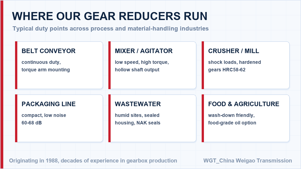
Installation Snapshots
Cement plant clinker belt
A cement plant drives its clinker transport belt with reducers in dusty, high-ambient conditions. Sealed housings and a 40 deg C maximum temperature rise let the units sit close to the kiln without extra cooling.
Paper mill pulp agitator
A paper mill uses reducers on pulp chest agitators. Continuous 24-hour duty is handled by lifetime lubrication, and the low backlash keeps the agitator steady when the stock consistency changes.
Selection Example: Tailings thickener rake drive at a copper mine
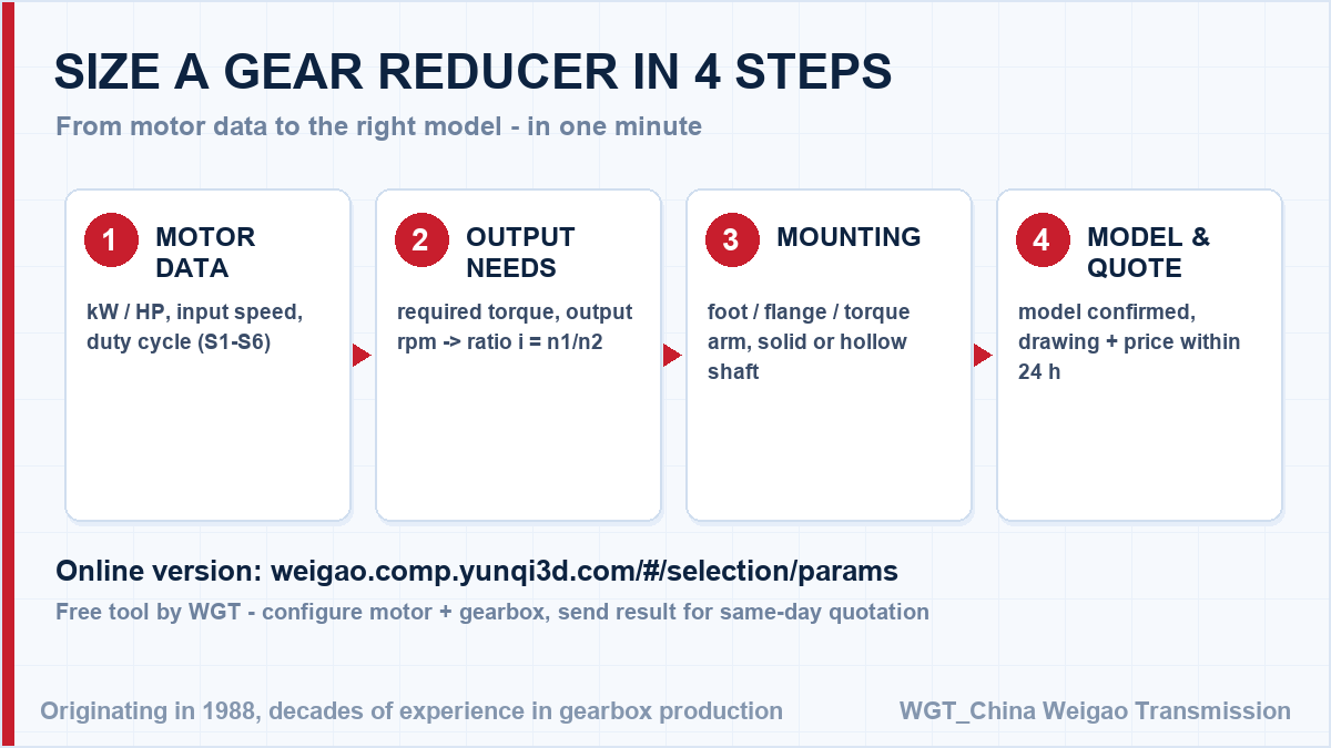
Take a 55 kW motor at 1480 rpm turning the rake at 12 rpm. The ratio follows directly: 1480 / 12 = 123, so a ratio near i=123 sits at the slow end of the two-stage band, and the frame is sized by the breakout torque a rake needs when it lifts out of consolidated underflow. In this case the widest foot-mounted vertical carries that breakout through a solid shaft with the thrust taken at the gearbox, and the bridge plate is drawn from the reaction torque figure supplied with the quotation. Use the same method for any frame in the series, then confirm the service factor with us - it is the one number buyers most often get wrong.
![speed reducer selection process diagram]()
The selection path we follow when checking your enquiry.
Technical Q&A
How do I calculate the ratio I need?
Divide motor speed by the target output speed (i = n1/n2), then check the required torque against the rating table with your service factor. The online selector below does this automatically.
Can the reducer be supplied with a brake motor or an IEC motor flange?
Yes. We supply the reducer as a bare unit with an IEC standard input flange, and you can bolt on any IEC or NEMA motor - including a brake motor. The flange dimensions follow the common IEC pattern, so existing motors drop straight on.
![speed reducer use cases across sectors]()
Typical installation environments for this gearbox family.
Get the Selection Checked - Free of Charge
Already picked a model? One screen in the WGT Motor & Gearbox Online Selection System is usually enough to pin down the frame size; we confirm the service factor afterwards.
Send us your calculated model and duty point. We cross-check the ratio, torque and service factor independently and confirm or flag the difference - a free second pair of engineer eyes. Looking for a gear reducer for screw conveyor? Tell us the duty point and we will confirm the model in writing.